Inverter apparatus comprising switching elements

a switching element and inverter technology, applied in the field of inverter apparatus, can solve the problems of element failure to turn off, and variable potential of the gate drive circuit, and achieve the effect of stabilizing the gate drawing curren

Inactive Publication Date: 2009-08-04
THE KANSAI ELECTRIC POWER CO
View PDF17 Cites 2 Cited by
  • Summary
  • Abstract
  • Description
  • Claims
  • Application Information

AI Technical Summary

Benefits of technology

[0010]Accordingly, the invention is proposed in view of the aforementioned problem. An object of the invention is to provide an inverter apparatus enabled to eliminate variation in potential-to-the-ground of the GTO element that corresponds to one of the phases and is performing a turn-off operation, which variation is caused by the switching operation of this GTO element corresponding to the other phase, and also enabled to stabilize the gate drawing current by surely achieving the turn-off of the GTO element.
[0014]According to the invention, the apparatus has the simultaneous switching prevention function. Thus, for example, a turn-on operation of each of the switching elements, which correspond to phases other than a phase corresponding to an optional one of the switching elements and also correspond to an electrode opposite to an electrode corresponding to the optional one of the switching elements, is delayed by a predetermined time in a case where a turn-on command signal for turning on each of the switching elements, which correspond to the other phases, is generated within a predetermined time period since the turn-off of the optional one of the switching elements. Consequently, the simultaneous switching of the switching elements corresponding to the other phases can be prevented. Thus, the variation in potential-to-the-ground of the GTO element can be prevented from occurring during a turn-off operation thereof. Also, the stabilization of the gate drawing current can be achieved by surely turning off the GTO elements.
[0016]According to the invention, the apparatus has the simultaneous switching prevention function. Thus, a turn-on or turn-off operation of each of the switching elements, which correspond to phases other than a phase corresponding to an optional one of the switching elements and also correspond to an electrode opposite to an electrode corresponding to the optional one of the switching elements, is delayed by a predetermined time in a case where a turn-on or turn-off command signal for turning off each of the switching elements, which correspond to the other phases, is generated within a predetermined time period since the turn-off or the turn-on of the optional one of the switching elements. Consequently, the simultaneous switching of the switching elements corresponding to the other phases can be prevented. Thus, for instance, the variation in potential-to-the-ground of the GTO element can be prevented from occurring during a turn-off operation thereof. The stabilization of the gate drawing current can be achieved by surely turning off the GTO elements. A high-quality inverter apparatus can be provided without causing a dc short circuit and a damage of the element.

Problems solved by technology

Thus, the aforementioned variation in the midpoint potential results in variation in the potential of the gate drive circuit.
In a case where the gate drawing current in that time becomes unstable due to the disturbance current as described above, the GTO element fails to turn off, and comes to be unable to turn off.
In the worst case, there is the possibility of damaging the GTO element.
Occurrence of the simultaneous switching of this GTO element corresponding to the other phase causes a problem that the gate drawing current becomes unstable.

Method used


Image

  • Inverter apparatus comprising switching elements
  • Inverter apparatus comprising switching elements
  • Inverter apparatus comprising switching elements

Examples


Embodiment Construction

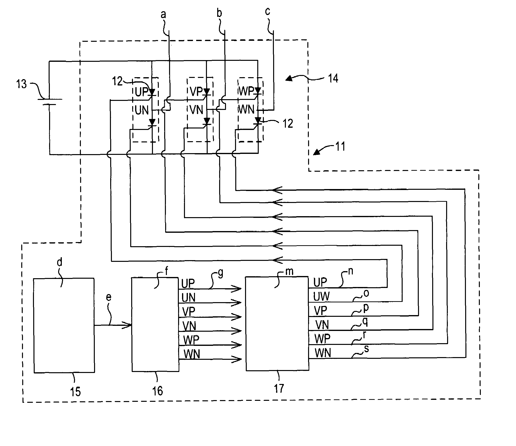
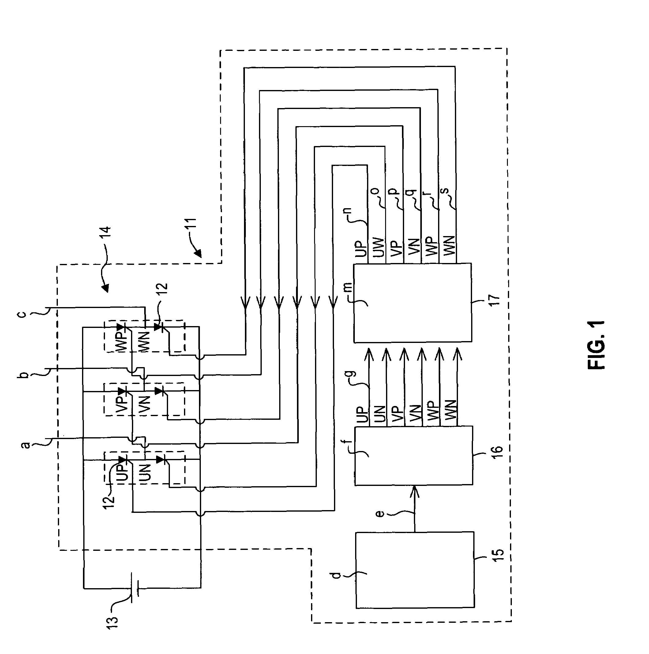
[0027]Hereinafter, an embodiment of an inverter apparatus according to the invention is described in detail. Incidentally, the following description of the embodiment describes a case where Si-GTO elements 12 are used as the switching elements (see FIGS. 1 and 2), and a case where SiC-GTO elements 22, which can operate at a higher temperature and a higher voltage than the Si-GTO elements 12 (see FIGS. 3 and 4).

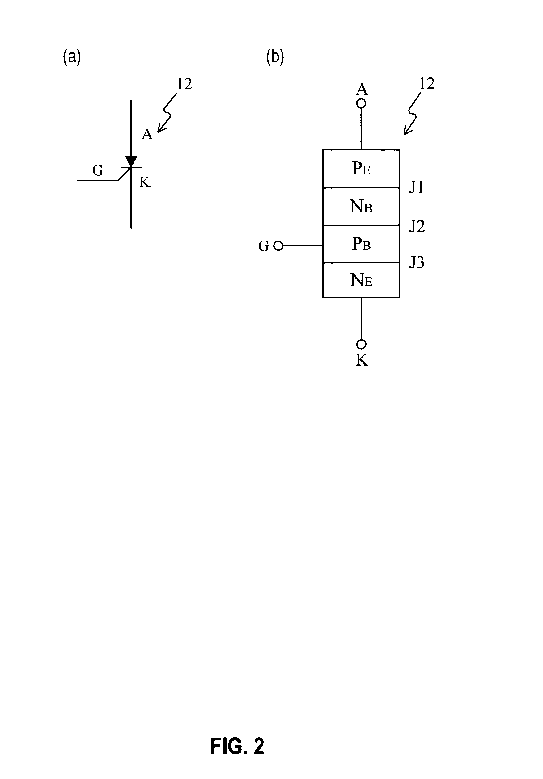
[0028]FIG. 1 exemplifies an inverter apparatus 11 using Si-GTO elements 12 as the embodiment. FIG. 2(a) shows the Si-GTO 12. FIG. 2(b) shows the internal structure of the Si-GTO 12. As shown in FIGS. 2(a) and 2(b), the Si-GTO element 12 has a pnpn structure obtained by bonding p-type semiconductor regions PE and PB and n-type semiconductor regions NB and NE and having junctions J1, J2, and J3, each of which are provided between the associated bonded regions. An anode A is drawn from the p-type semiconductor region PE. A cathode K is drawn from the n-type semiconductor region N...


PUM


Abstract

A problem to be solved by the present invention is to eliminate variation in potential in a turn-off time period of each GTO element, and to stabilize a gate drawing current by surely performing the turn-off of the GTO element. In an inverter apparatus having a three-phase inverter configured to include paired GTO elements an inverter control portion has a simultaneous switching prevention function of delaying a turn-on operation of each of the GTO elements which correspond to phases other than a phase corresponding to an optional one of the GTO elements and also correspond to an electrode opposite to an electrode corresponding to the optional one of the GTO elements by a predetermined time in a case where a turn-on command signal for turning on each of the GTO elements is generated within a predetermined time period since the turn-off of the optional one of the GTO elements.

Description

TECHNICAL FIELD[0001]The present invention relates to an inverter apparatus enabled to prevent a simultaneous switching operation of switching elements, which are used and constitute a three-phase inverter incorporated in, for example, a large-capacity UPS, a battery energy storage system, or the like, from occurring during each of the switching elements performs an on / off operation.BACKGROUND ART[0002]A three-phase inverter serving as a kind of an electrical power converter incorporated in, for example, a large-capacity UPS, a battery energy storage system, or the like is adapted to perform the conversion of a dc voltage supplied from a dc power supply E, such as a solar battery and a fuel cell, into an ac voltage and to supply electric power to loads UL, VL, and WL, as shown in FIG. 7. The three-phase inverter has a structure in which paired switching elements, which are arranged in an up / down direction, as viewed in this figure, and which correspond to each of a U-phase, a V-phas...

Claims


Application Information

Patent Timeline
Patent Type & Authority Patents(United States)
IPC IPC(8): H02M7/5387H02M7/48
CPCH02M7/521H02M1/38H02M1/32H02M2001/0012H02M1/0012
Inventor SUGAWARA, YOSHITAKAASANO, KATSUNORIMATSUKAWA, MITSURUMINOWA, YOSHIFUMISHIKATA, TOSHIHIKO
Owner THE KANSAI ELECTRIC POWER CO
Why Eureka
Try Eureka