Directional antenna system for wireless X-ray devices

a wireless x-ray and antenna system technology, applied in the field of wireless x-ray devices employing a directional antenna system, can solve the problems of physical constraints, not actual data, and the patient's orientation during the x-ray imaging procedure, and achieve the effect of low power

Inactive Publication Date: 2009-07-28
GENERAL ELECTRIC CO
View PDF8 Cites 7 Cited by
  • Summary
  • Abstract
  • Description
  • Claims
  • Application Information

AI Technical Summary

Problems solved by technology

One problem with a wireless system is interference, either passive created by a physical obstacle or obstruction, or active which is created by another signal source.
Additionally, the wireless system must be able to operate with unobtrusive antennae, and typically with power from a standard internal wall outlet.
However, the physical phenomena of interference and attenuation of RF signals or waves provided physical constraints, not the actual data.
However, oftentimes a problem with the patient's orientation during the x-ray imaging procedure is not apparent until after the imaging procedure is completed and the x-rays are viewed.
One problem with conventional x-ray systems is improper patient positioning that prevents the radiologist or technician from successfully imaging the desired areas.
Improper patient placement can also create passive interference that will affect the wireless signals traveling between a transmitter and a receiver.
Further, another aspect with conventional x-ray systems is the lack of any real time-of-session feedback concerning the necessary strength of the x-ray beam required to successfully image the target area of a patient.
X-rays, even in small amounts, cause damage to living tissues.
Unfortunately, oftentimes a radiologist must insure complete imaging at the cost of boosting the strength of the radiation beam.

Method used


Image

  • Directional antenna system for wireless X-ray devices
  • Directional antenna system for wireless X-ray devices
  • Directional antenna system for wireless X-ray devices

Examples


first embodiment

[0025]In the invention, the directional antennae system only uses one directional antenna (either 110 or 120) that are attached to the body of the x-ray tube 100. The one directional antenna, 110 or 120, attached to the body of the x-ray tube 100, would transmit (send RF energy) towards the wireless x-ray detector 140. The transmitted RF signal from directional antenna 110 or 120 would be received by the single directional antenna 150.

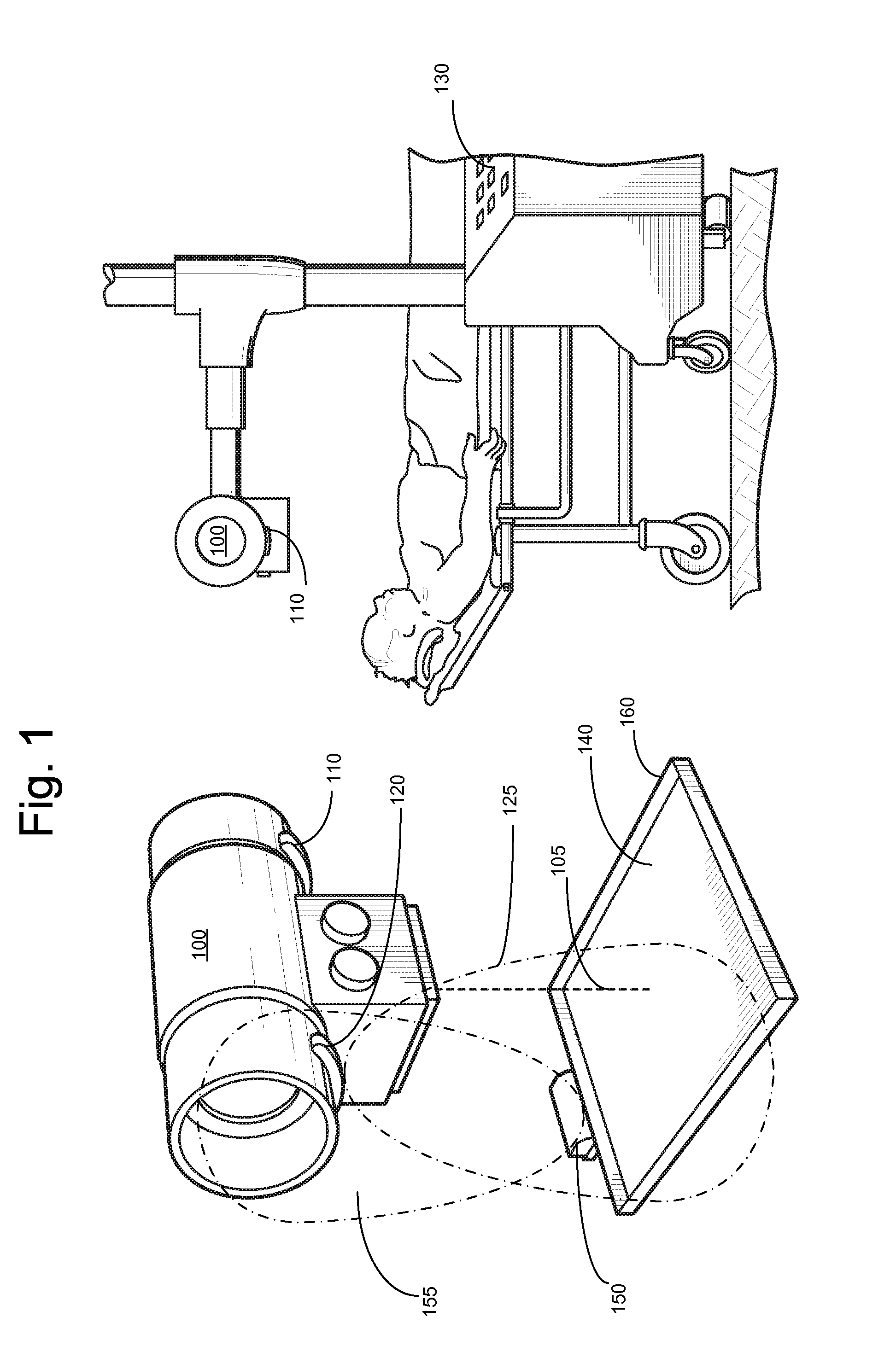
[0026]As shown in FIG. 1, the directional antenna 120 has a primary transmission path 125. Additionally, the directional antenna 150 has a primary transmission path 155. The wireless x-ray detector 140 may be located on a panel 160 that is placed beneath the radiology patient. Further, the directional antenna 150 may be located on panel 160. The position of the directional antenna 150 may be for example, on the periphery of the panel 160, at such a location where a radiology patient would not block or otherwise interfere with the directional antenna 15...

second embodiment

[0040]In the invention, the directional antenna system uses one directional antenna (either 110 or 120) that are attached to the body of the x-ray tube 100. The one directional antenna, 110 or 120, attached to the body of the x-ray tube 100, would transmit (send RF energy) towards the wireless x-ray detector 140. The transmitted RF signal from directional antenna 110 or 120 would be received by the single omni-directional antenna 170.

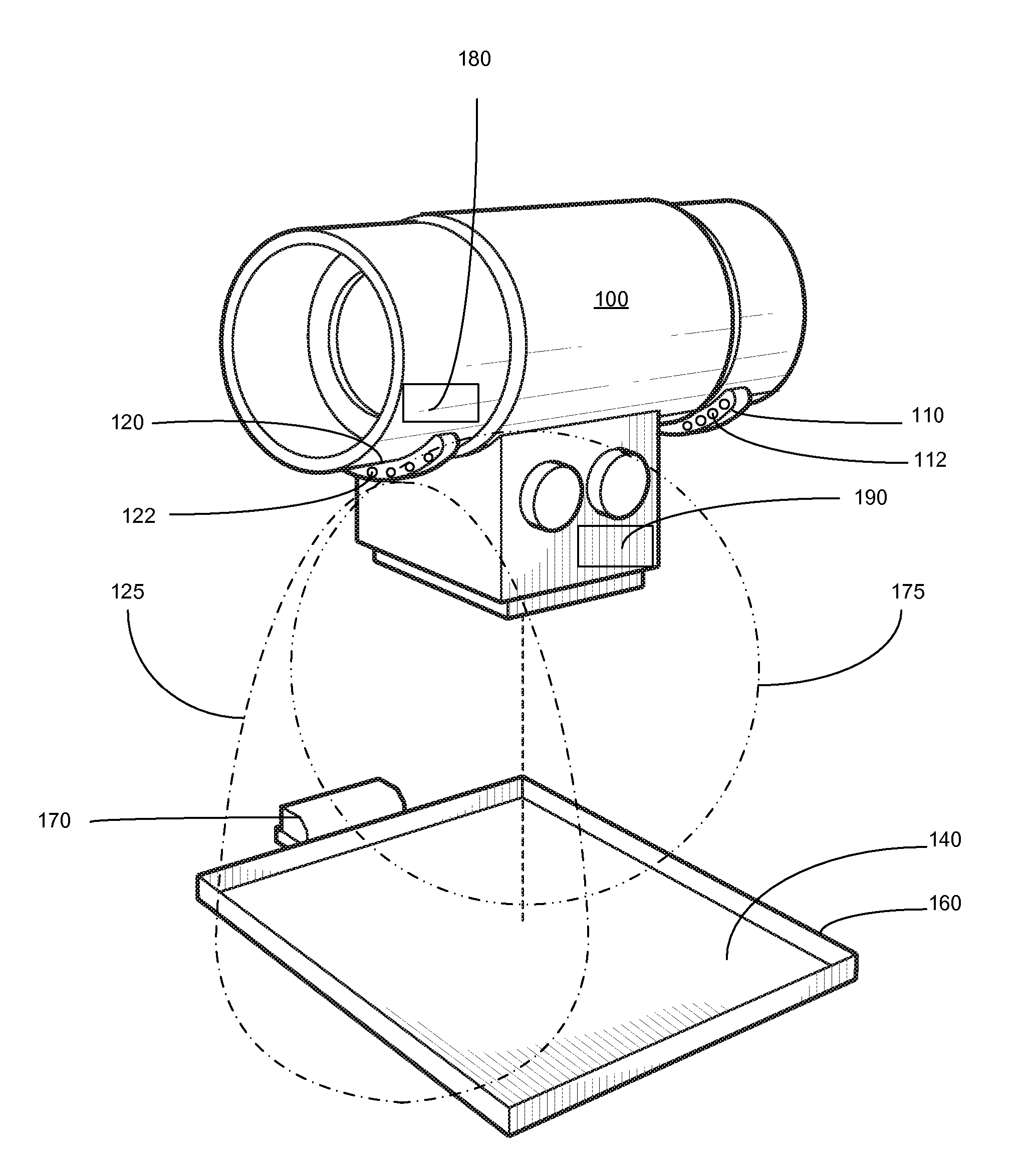
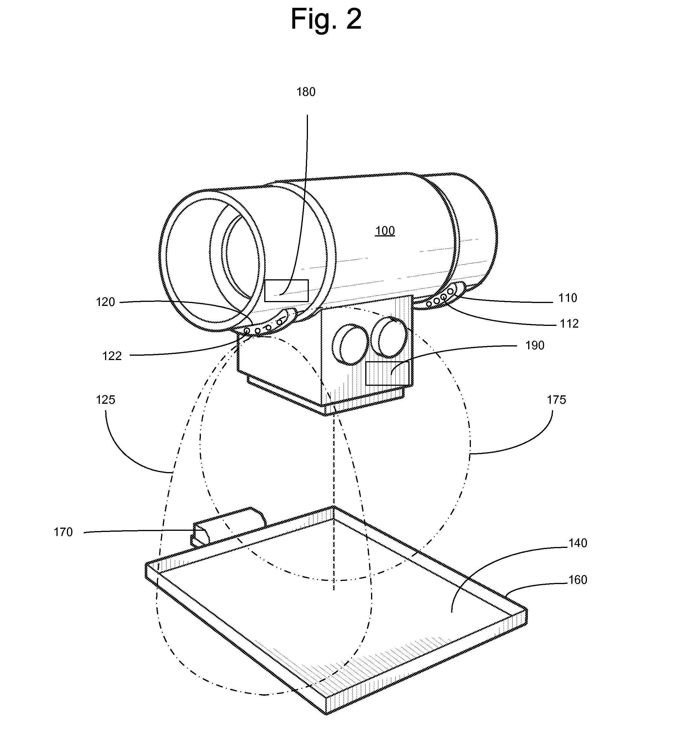
[0041]As shown in FIG. 2, the directional antenna 120 has a primary transmission path 125. Additionally, the omni-directional antenna 170 has a primary transmission path 175 (an omni-directional antenna generates a general, radial in all directions, expanding transmission path). The wireless x-ray detector 140 may be located on a panel 160 that is placed beneath the radiology patient. Further, the omni-directional antenna 170 may be located on panel 160. The position of the omni-directional antenna 170 may be for example, on the periphery of the panel 1...


PUM


Abstract

Systems and techniques are provided for a directional antenna system that employs a wireless link between x-ray apparatus. The system includes a host computer, an x-ray tube with an emission scan channel, a first directional antenna connected to the x-ray tube and with an orientation parallel to the emission channel, a second antenna wirelessly communicating with the first directional antenna, an x-ray detector wirelessly communicating with the x-ray tube, and a rigid panel supporting the second antenna and the x-ray detector being in contact with the emission scan channel. Specific techniques are employed to manage antenna direction and transmission.

Description

BACKGROUND OF THE INVENTION[0001]1. Field of Invention[0002]This invention relates generally to wireless x-ray devices, and more particularly to wireless x-ray devices employing a directional antenna system.[0003]2. Description of Related Art[0004]Conventional wireless systems are becoming more prevalent with applications that previously had to operate with wired connections. Wireless technology includes applications spanning single peer-to-peer connections, to broadly diverse wireless networks (e.g., WLAN). Further, wireless systems operate in conjunction with environments that support more than one discrete wireless system, and must therefore be able to effectively operate within the wireless confluence and the available wireless resources, (e.g., communication bandwidth).[0005]In these conventional wireless systems, the individual wireless signals oftentimes interfere with each other. Further, wireless signals also compete with non-wireless sources that by virtue of an electric c...

Claims


Application Information

Patent Timeline
Patent Type & Authority Patents(United States)
IPC IPC(8): H05G1/28
CPCA61B6/00
Inventor SERCEKI, ZELJKO JOHNSEXTON, DANIEL WHITE
Owner GENERAL ELECTRIC CO
Why Eureka
Try Eureka