
Kayak portaging device

a portaging device and kayak technology, applied in the field of kayak portaging devices, can solve the problems of slow and difficult process of kayak portaging and transport, inaccessible solo kayakers, and inability to carry kayaks over long distances, etc., and achieve the effect of quick, comfortable and safe manner

Inactive Publication Date: 2009-07-21
MORRIS KEITH
View PDF5 Cites 6 Cited by
  • Summary
  • Abstract
  • Description
  • Claims
  • Application Information

AI Technical Summary

Benefits of technology

[0016]It is an object of this invention to provide a compact, lightweight, portaging device which will attach as an integral component to a kayak and is not unattached for storage.
[0017]It is a further object of this invention to provide a simple portaging device which can rotate between a portaging position and a storage position.
[0018]It is another object of this invention to provide a portaging device which will not interfere with paddling a kayak while still attached in the storage position.
[0019]It is an object of this invention to provide a comfortable device which acts as a backrest for the paddler of a kayak while in the storage position.
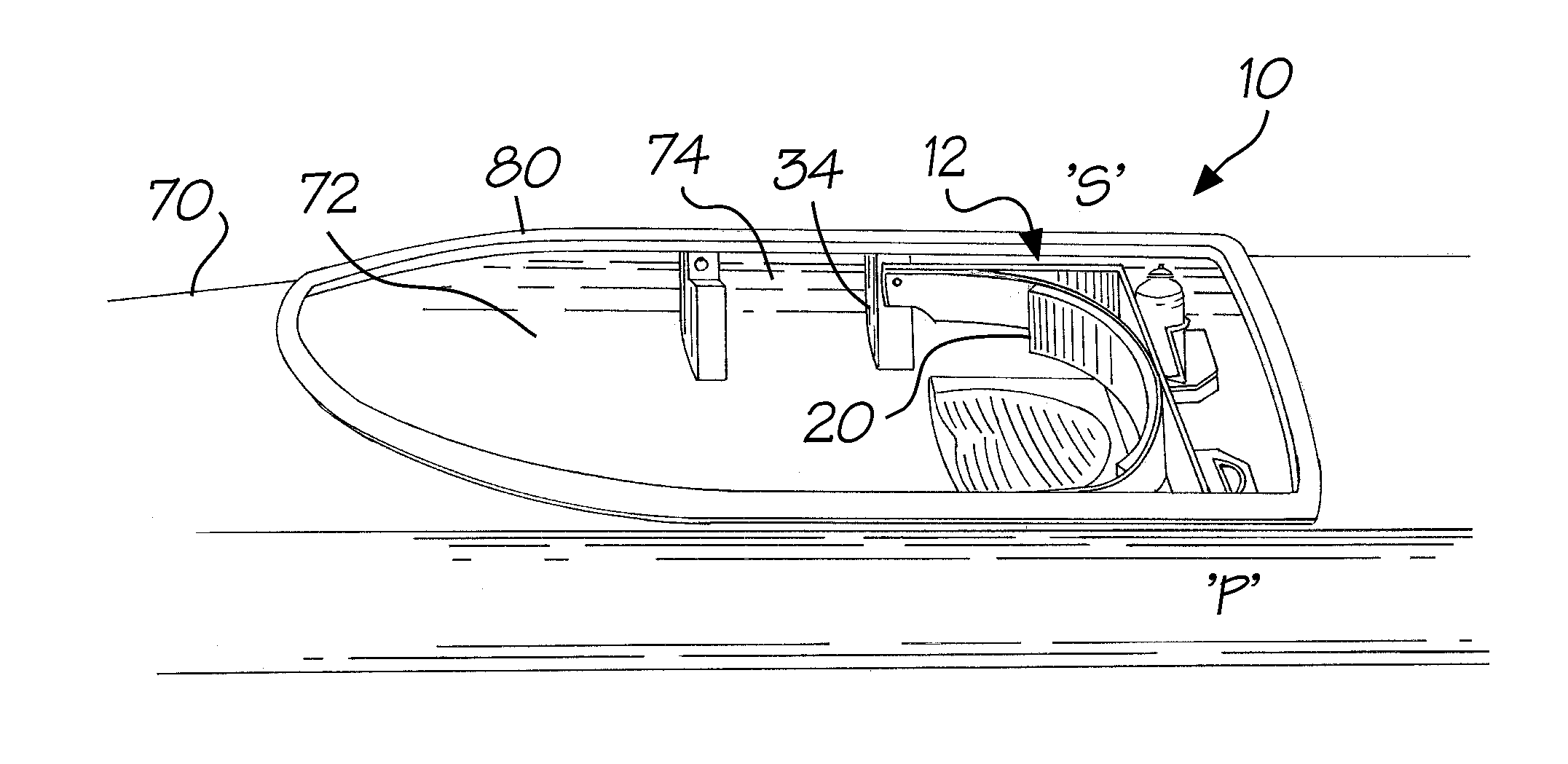
[0023]The kayak portaging device presents a quick, comfortable, safe manner for carrying a kayak over varying distances such as would be found portaging from lake to lake. By incorporating the seat backrest into the yoke design, the carrying device becomes an integral part of the kayak. With the kayak portaging device there are no separate loose pieces which must be attached by screws, ropes, bungies, or other mechanical means, then removed and stored on or within the kayak when not in use. The kayak portaging device is very safe and simple, comprised of only one moving part, which when deployed in its carry / portaging position, rests against two positive stops. When rotated into the carry / portaging position, two small powerful magnets in the yoke frame / backrest, and two powerful magnets located just above the positive stops, hold the portaging device in position while the kayak is lifted and placed on the carrier's shoulder. Once placed on the carrier's shoulders, the weight of the kayak against the positive stops hold the portaging device in position while in use. The yoke frame / backrest can be engaged from its stored position and rotated to its useable position in a matter of seconds and can be disengaged just as easily.

Problems solved by technology

Kayaks as a watercraft are not designed to be easily portaged or carried over long distances.
Not only carrying the kayak, but the removal and subsequent repacking of items stored within the kayak, through small hatches makes moving and transport of the kayak a slow, difficult process.
This method is not available to the solo kayaker, who must rely on some other method or device for portaging a kayak, and is not considered relevant.
This manner of portaging is uncomfortable over longer distances and results in an unequal distribution of weight on the carriers muscles and skeletal structure.
This yoke, if not removed, would interfere with cockpit access and use by the paddler.
A carrying yoke of this design may be easily lost, misplaced, or simply forgotten.
These devices are not simple to use, requiring attachment to and unattachment from the kayak for use, and the rigging of weight distributing poles or straps.
These devices work well on flat level surfaces, but become difficult, or impossible to use if the terrain becomes rocky, steep or uneven.
These devices do not work well under adverse conditions.
The Gonda device is not designed for use in a kayak.
The Cerkvenik device is not designed for use in a kayak.
The Miller device is not designed for use in a kayak.
All of the above listed patents refer to devices which, if modified to mount in a kayak, would interfere with a kayaker while paddling, and would require attaching only for carrying, and would require unattaching for paddling.

Method used


Image

  • Kayak portaging device
  • Kayak portaging device
  • Kayak portaging device

Examples


Embodiment Construction

[0037]Reference is made herein to the attached drawings. Like reference numerals are used throughout the various drawings to depict like or similar elements of the claimed portaging device. For the purpose of presenting a brief and clear discussion of the portaging device, the preferred embodiment will be discussed primarily as depicted for use in a kayak. This is for representative purposes only and should not be construed as limiting the adaptation and use of this device in other types of suitable watercraft.

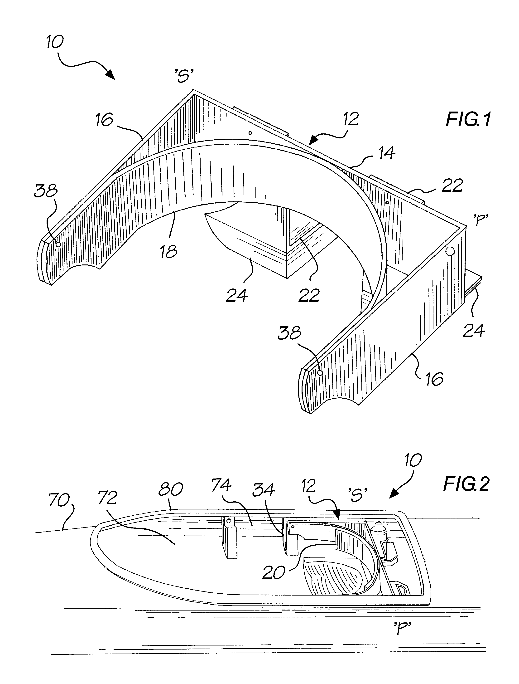
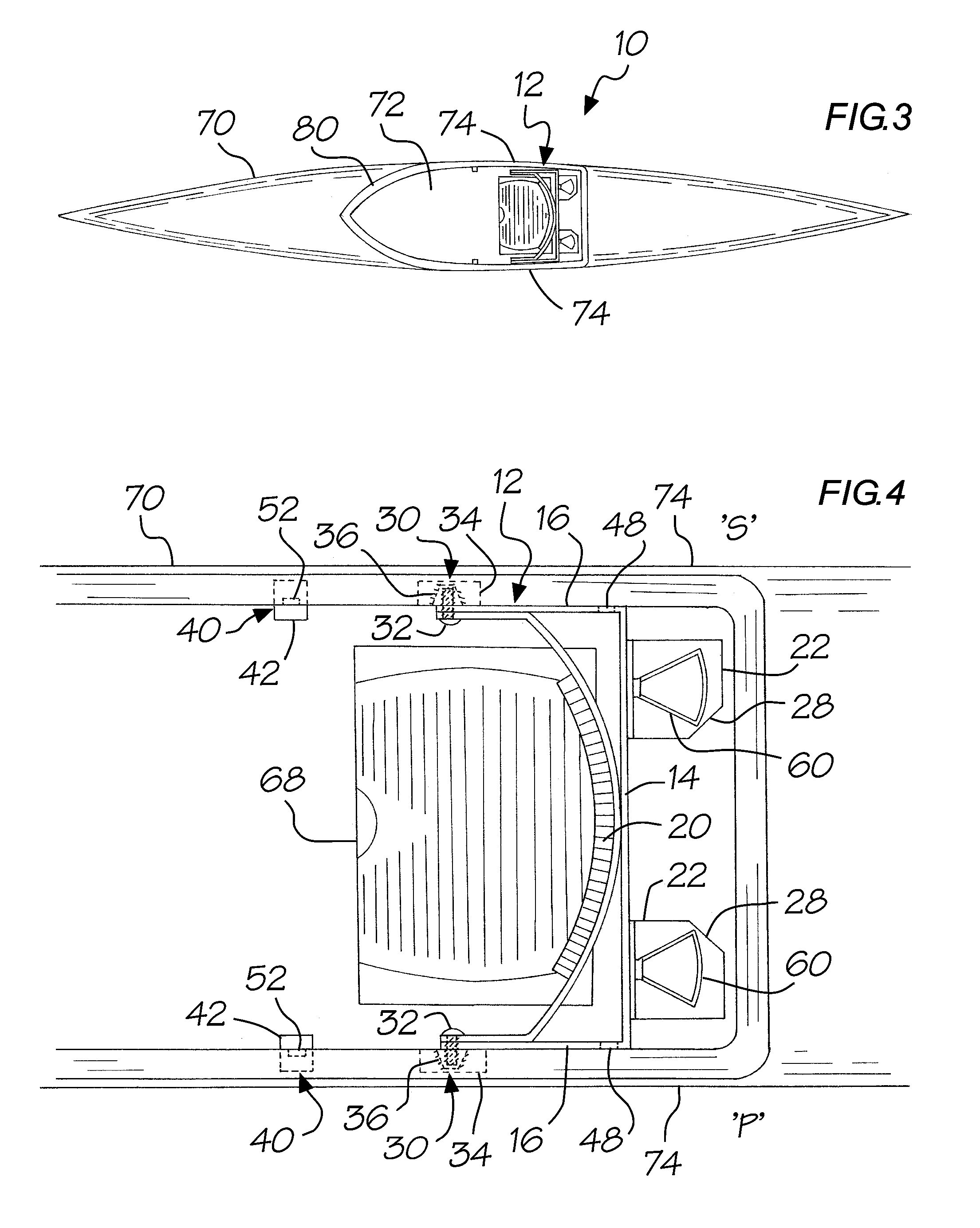
[0038]The preferred embodiment of the kayak portaging device 10 is a u-shaped device which generally includes a yoke frame / backrest assembly 12 as can be seen in FIG. 1, a pivot assembly 30 as can be seen in FIG. 4, a stop / lock assembly 40 as can be seen in FIG. 4, and a pair of bottle holders 60 as can be seen in FIG. 4.

[0039]Referring now to FIG. 1, the yoke frame / backrest assembly 12 is seen as it would appear when in the storage / backrest position, stowed behind the kayak s...


PUM


Abstract

A kayak portaging device which incorporates a seat backrest into the yoke design, making the portaging yoke an integral part of the kayak. A u-shaped device, with a transverse yoke frame, and parallel pivot arms extending from the ends of the yoke frame to pivot points on the kayak hull forward of the seat. A curved backrest is incorporated within the u-shaped device. The device rotates from a backrest position behind the kayak seat for use while paddling, forward to an inverted position over the kayak's center of gravity for portaging. “L” brackets with padded ends are mounted on the backside of the yoke frame extending downwards. Bottle holders attached to the “L” brackets are accessible to a seated kayaker. When rotated to the inverted portaging position, pivot arms are held against positive stops by a magnetic catch, and “L” brackets now extend upwards providing elevated shoulder rests for portaging.

Description

BACKGROUND OF THE INVENTION[0001]The invention relates to a kayak portaging device, and specifically to a pivoting kayak portage yoke, which can rotate from a position behind the kayak seat for storage while paddling, forward to an inverted position over the kayak's center of gravity for carrying. With the incorporation of a seat backrest into the design of the portage yoke, the device acts as a backrest for a kayaker while paddling, when it has been placed in the storage / backrest position.[0002]Kayaks as a watercraft are not designed to be easily portaged or carried over long distances. Not only carrying the kayak, but the removal and subsequent repacking of items stored within the kayak, through small hatches makes moving and transport of the kayak a slow, difficult process.[0003]A common manner for carrying a kayak is by means of two rope handles, one attached to the bow and the other attached to the stern. With this method, two people are required to perform the task of lifting ...

Claims


Application Information

Patent Timeline
IPC IPC(8): B63B35/71
CPCB63B35/71B63B2035/715B63B34/26B63B34/20
Inventor MORRIS, KEITH
Owner MORRIS KEITH
Learn More