
Wind energy system and method of operation thereof

a wind energy system and wind energy technology, applied in the direction of active/predictive/anticipative control, electric generator control, machines/engines, etc., can solve the problems of high contractual penalties for producers, strong economic pressure on the operation of modern wind energy systems, and high contractual penalties for operators of wind energy systems. , to achieve the effect of significantly higher average annual yield

Active Publication Date: 2009-07-14
GENERAL ELECTRIC CO
View PDF24 Cites 37 Cited by
  • Summary
  • Abstract
  • Description
  • Claims
  • Application Information

AI Technical Summary

Benefits of technology

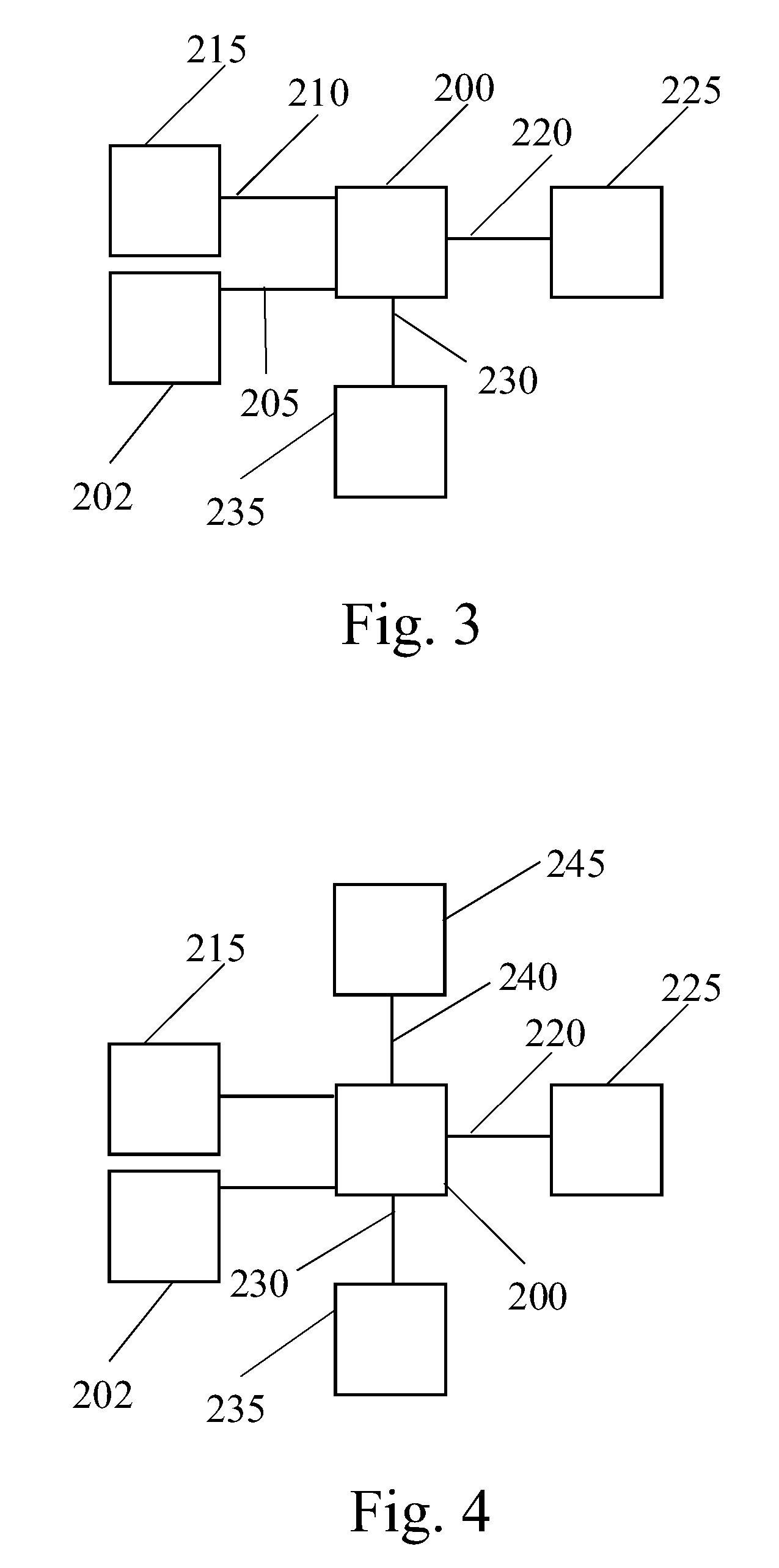
The present invention provides a method for operating a wind energy system by measuring yield parameters and condition parameters, calculating optimized values of operational parameters based on the measurement results and historical data, and resetting the operational parameters to the optimized values. The method can improve the average annual yield of the wind energy system and can be used in existing wind energy systems as a retrofit package. The invention also provides a wind energy system with a sensor unit for measuring yield parameters and condition parameters, actuators for adjusting adjustable parts of the wind energy system, and a self-learning controller for optimizing operational parameters. The wind energy system can also be connected in a wind park with other wind energy systems for data interchanging and learning from each other.

Problems solved by technology

The operation of modern wind energy systems underlies strong economic pressures.
Often, wind energy system producers have to give warranty on the energy yield of a wind energy system.
If the yield of a wind energy system in operation turns out to be below the yield value which was promised, the producers have to pay high contractual penalties to the operators of the wind energy system.
However, despite this setting, experience shows that wind energy systems very often still run sub-optimally.

Method used


Image

  • Wind energy system and method of operation thereof
  • Wind energy system and method of operation thereof
  • Wind energy system and method of operation thereof

Examples


Embodiment Construction

[0029]Reference will now be made in detail to the various embodiments of the invention, one or more examples of which are illustrated in the figures. Each example is provided by way of explanation of the invention, and is not meant as a limitation of the invention. For example, features illustrated or described as part of one embodiment can be used on or in conjunction with other embodiments to yield yet a further embodiment. It is intended that the present invention includes such modifications and variations.

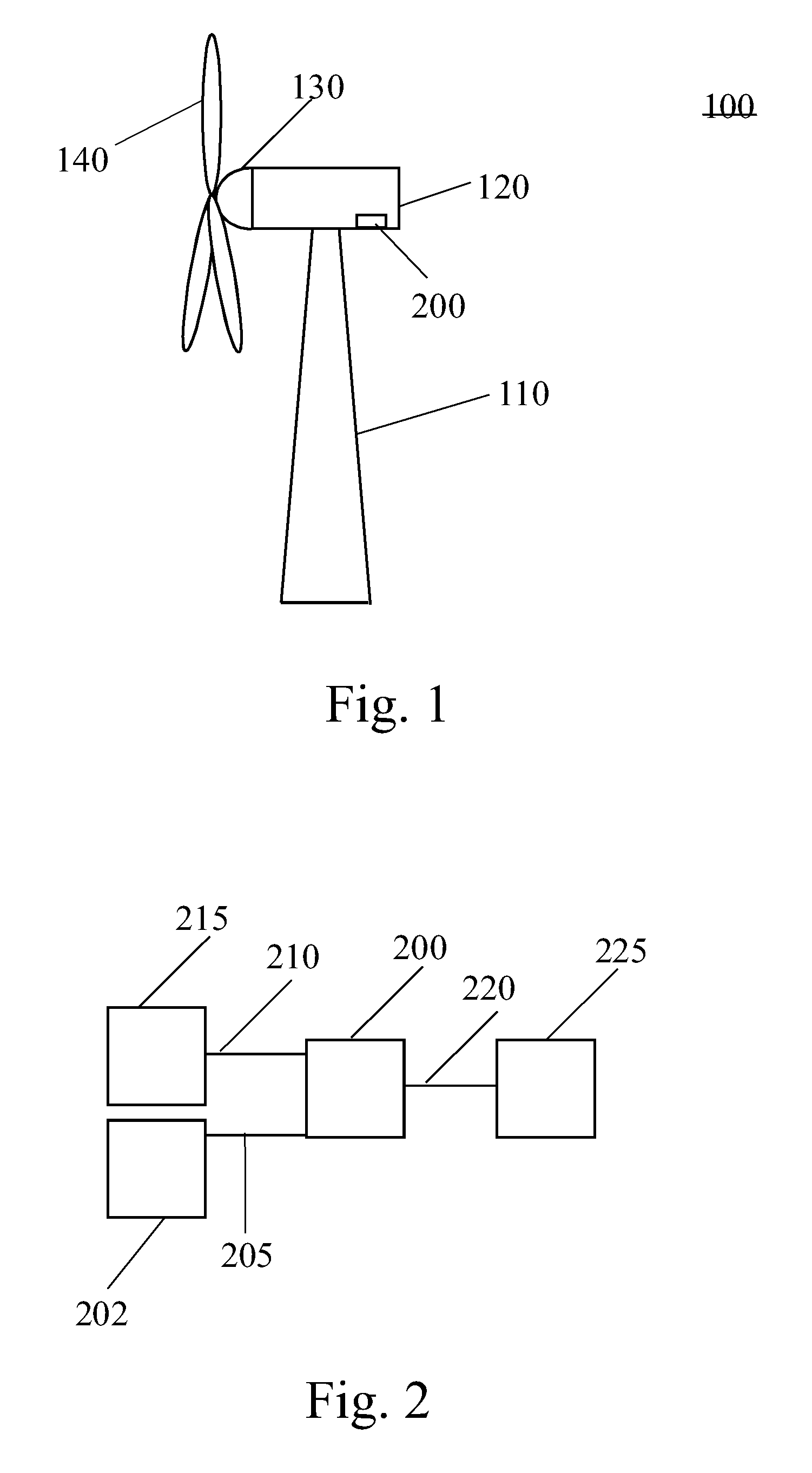
[0030]FIG. 1 is a schematic view of a wind turbine. The wind turbine 100 includes a tower 110 to which a machine nacelle 120 is mounted at its top end. The nacelle houses a drive train to which a main electric generator is connected (not shown). A hub 130 bearing three rotor blades 140 is mounted to a lateral end of the machine nacelle 120. The rotor blades 140 can be adjusted by pitch drives which are typically accommodated inside hub 130. The rotor blades 140 should be instal...


PUM


Abstract

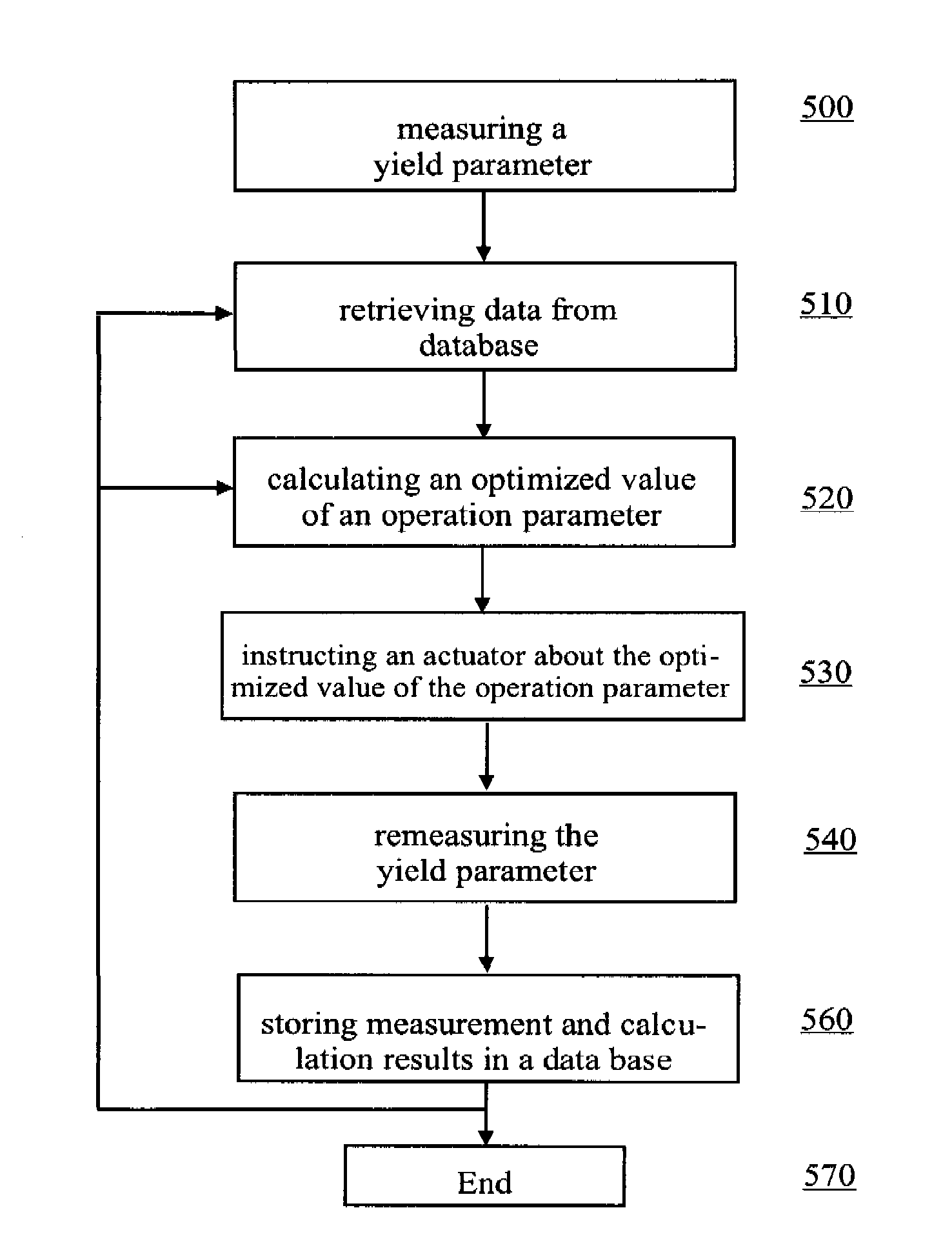
A method for operating a wind energy system is provided comprising the steps of setting the value of an operational parameter of the wind energy system, measuring a yield parameter of the wind energy system and measuring a condition parameter. Further, the method comprises the step of calculating an optimized value of the operational parameter based on historical data and the outcome of the measurements. The method further comprises the step of resetting the operational parameter to the optimized value of the operational parameter wherein the resetting is such that the yield parameter is optimized. Further, a wind energy system is provided having a sensor unit for measuring a yield parameter of the wind energy system, a sensor for measuring a condition parameter, an actuator for adjustment of at least one adjustable part of the wind energy system, and a self-learning controller. The self-learning controller is connected to the sensor unit and the actuator and receives measurement data from the sensor unit. The self-learning controller performs optimization calculations based on the measurement data and sends instruction signals to the actuator based on the outcome of the optimization calculations for the adjustment of the adjustable part of the wind energy system. The instruction signals are such that the yield parameter is optimized.

Description

FIELD OF THE INVENTION[0001]The present invention relates to a wind energy system and a method of operation thereof.BACKGROUND OF THE INVENTION[0002]The operation of modern wind energy systems underlies strong economic pressures. Often, wind energy system producers have to give warranty on the energy yield of a wind energy system. If the yield of a wind energy system in operation turns out to be below the yield value which was promised, the producers have to pay high contractual penalties to the operators of the wind energy system.[0003]It is therefore typical that wind energy systems are operated such that a high yield can be expected. In order to do so, the multitude of parameters for the operation of a wind energy system, which can be set and adjusted when the wind energy system is operated, is set to the values that are expected to provide for a maximum yield. However, despite this setting, experience shows that wind energy systems very often still run sub-optimally.BRIEF DESCRI...

Claims


Application Information

Patent Timeline
Patent Type & Authority Patents(United States)
IPC IPC(8): F03D9/00H02P9/04
CPCF03D7/0204F03D7/0272F03D7/0292F03D7/046F03D7/0224Y02E10/723F05B2240/96F05B2270/1033F05B2270/20F05B2270/32F05B2270/321F05B2270/322F05B2270/323F05B2270/324F05B2270/335F05B2270/404F05B2270/708Y02E10/72
Inventor SCHELLINGS, VINCENT
Owner GENERAL ELECTRIC CO
Learn More