
Unmanned aerial vehicle and launch assembly

a launch assembly and unmanned aerial technology, applied in the field of unmanned aerial vehicles (uavs), can solve the problems of high cost of each, inherently costly manufacturing and assembly, and inability to achieve high-quality, reliable and reliable launch equipmen

Active Publication Date: 2009-07-07
NORTHROP GRUMMAN SYST CORP
View PDF21 Cites 62 Cited by
  • Summary
  • Abstract
  • Description
  • Claims
  • Application Information

AI Technical Summary

Benefits of technology

[0007]Briefly, and in general terms, the invention provides an unmanned aerial vehicle (UAV) that is cost effective to use and manufacture. The UAV includes an airframe assembly having a low count of component parts, thereby contributing to overall cost-effectiveness. The UAV is reusable and can carry a variety of payloads, making it highly adaptable for use in a variety of applications, including military and civilian applications. Nonetheless, the UAV can be fabricated at sufficiently low cost, allowing mission planners to use the UAVs in a disposable manner. Moreover, many of the UAVs can be packaged in a single container for convenient storage, transportation and rapid deployment, further promoting the versatility of the system.
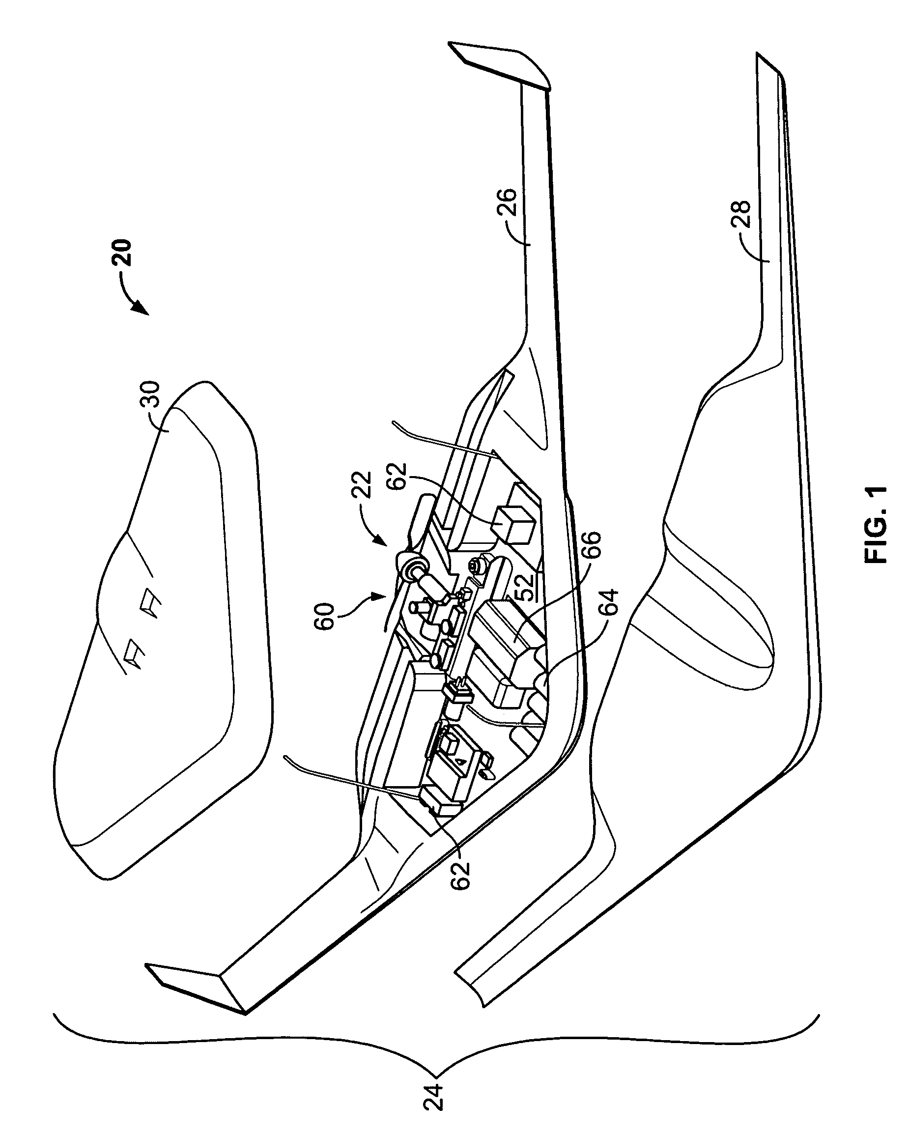
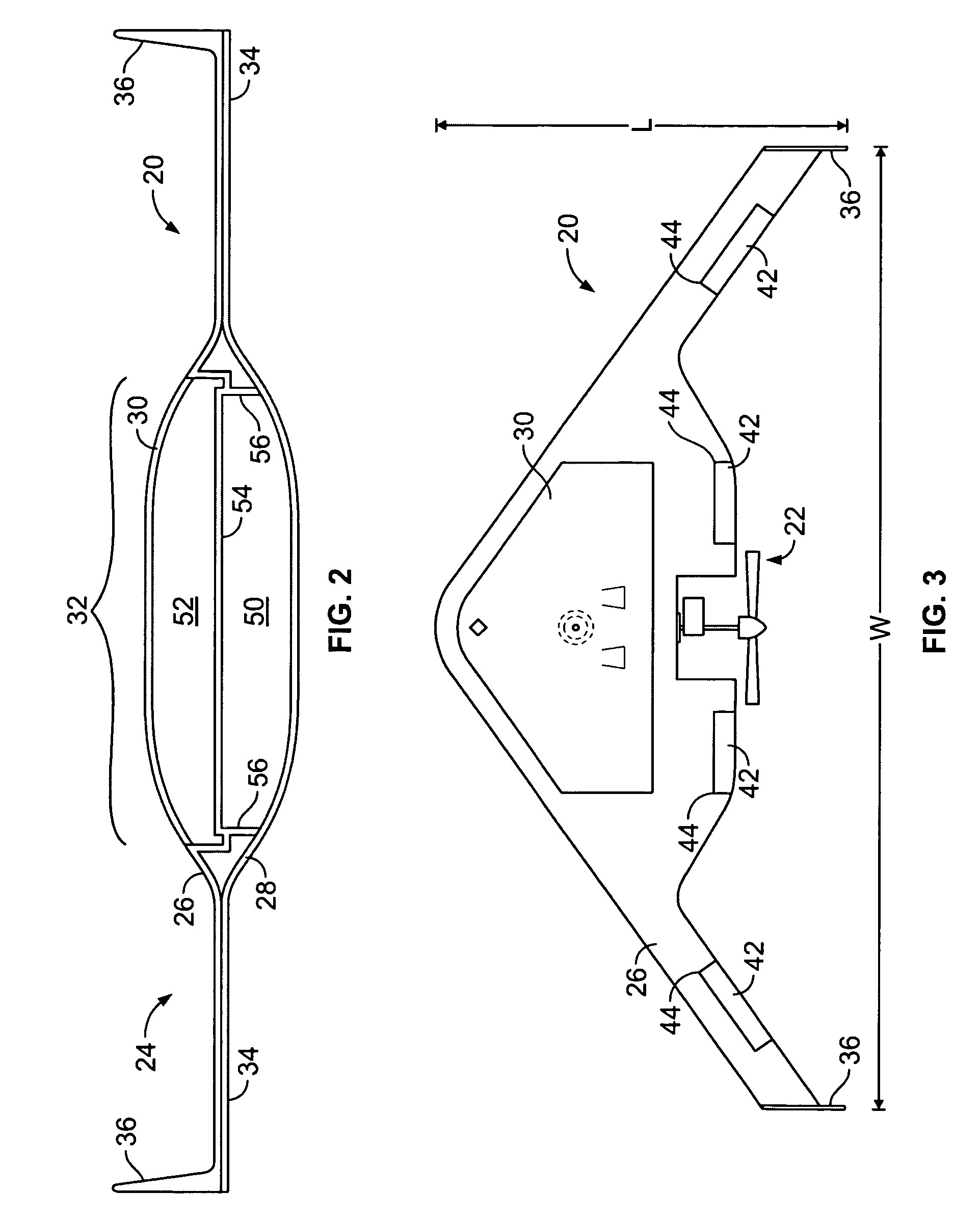
[0008]More specifically, and by way of example only, the UAV includes conforming shells, e.g., a lower shell, an upper shell and a payload cover, that combine to form the airframe. The lower and upper shells mate such that interior walls define a fuel tank and a payload bay within the airframe. Thus, separate structures are not needed to form the fuel tank and the payload bay. Rather, they are formed coincident with the airframe, contributing to ease of assembly and other cost savings. Due in part to the configuration of the components, e.g., the payload cover, the upper shell and the lower shell, inexpensive molding process can be used. For example, they can be formed in shallow one-piece molds suitable for composite lay-up, vacuforming, or blow-molding, or other economical high-production techniques.
[0015]Systems and methods of conveniently storing and rapidly deploying UAVs are also provided. In an independent aspect of the invention, multiple UAVs are stored in a single container. The container includes a container body having an opening and a removable lid covering the opening. The container can further include alignment supports, such as a conformed liner, that facilitates proper positioning of the UAVs within the container. The container may further include a deployment mechanism that initiates rapid ejection of the UAVs from the container. Thus, the container can serve as both a storage container and a launch platform.
[0016]In a detailed aspect of an exemplary embodiment, the container includes ejection charges and a piston located at a second end thereof to facilitate rapid deployment of the UAVs. The piston is disposed between the ejection charges and the aircraft. Upon ignition of the ejection charges, the piston drives outward toward the opening of the container causing the lid to open and the entirety of the UAVs to eject from the container. In this manner, the entire contents of the container can be rapidly deployed.
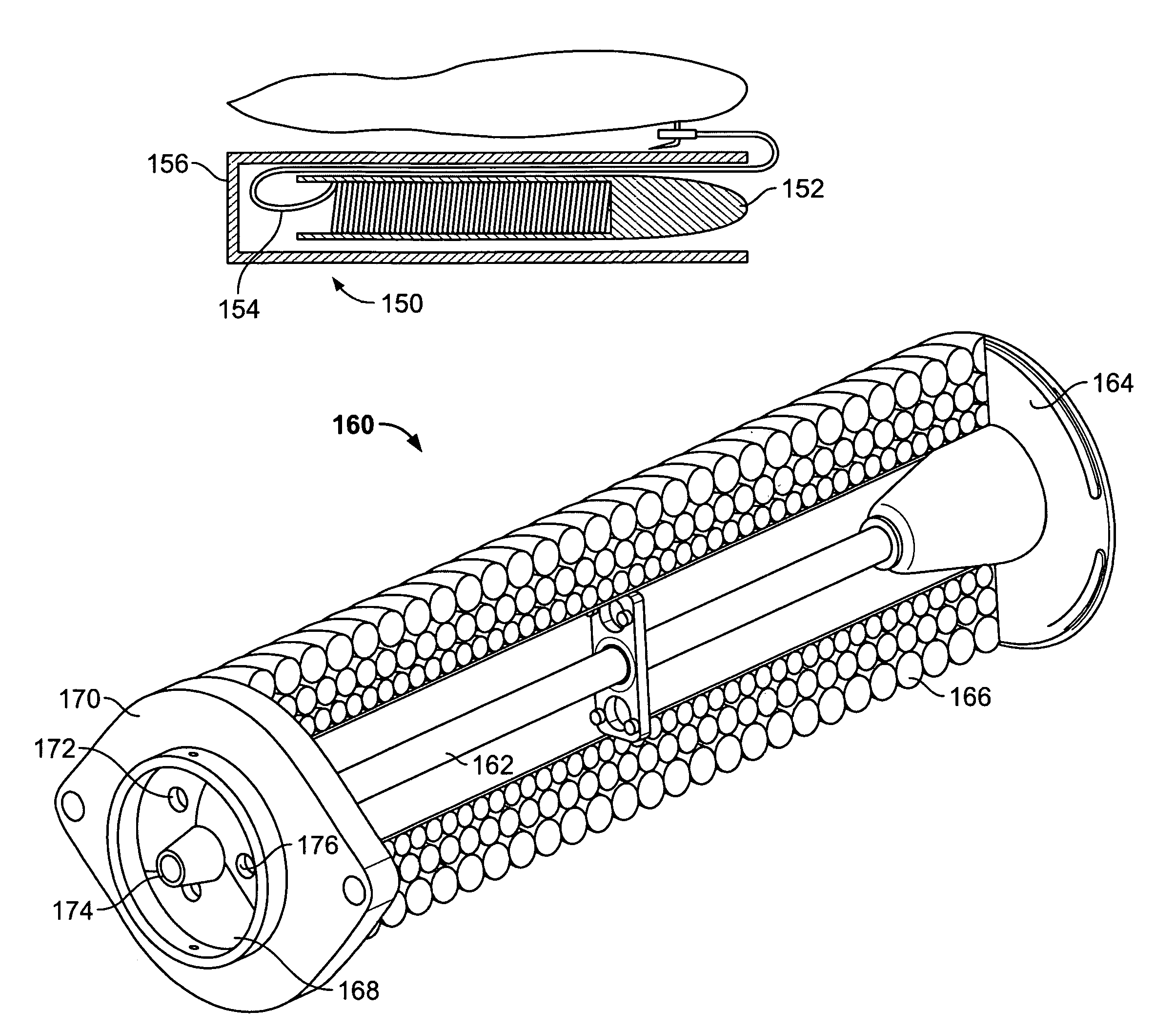
[0017]In another independent aspect of the invention, a launcher is provided that deploys a UAV without need of a runway or excessive acceleration. The launcher is compact and easy to use. In an exemplary embodiment, the launcher includes an elastic tether connecting the UAV to an accelerated mass, e.g., a shell. Various approaches can be used to accelerate the shell. In an exemplary embodiment, the shell is discharged from a closed volume via a pressurized gas or ignition of a combustible fuel. For example, aviation, marine or automotive fuel can be used, facilitating ease of use for forward deployed troops since such fuels are readily accessible. In use, the shell is rapidly accelerated, uncoiling the tether attached thereto. Once the tether is fully tensioned, the UAV accelerates away from the launcher. Stretching of the tether delivers a gentle acceleration to the vehicle over a distance. As the UAV picks up energy, the shell loses energy, decelerates, and the tether slackens. Once the tether is slacked, the tether detaches from the vehicle.

Problems solved by technology

Such UAVs typically include multi-part wings, control surfaces, and a multi-part fuselage, requiring precise fittings of many joints, making them inherently costly to manufacture and assemble.
However, due in part to the relative high cost for each UAV, this loitering mission is typically performed by a single UAV, or a limited number of UAVs.
If the enemy successfully strikes a limited number of UAVs, tactical surveillance can be compromised and, due in part to deployment constraints of the UAV, there can be a relatively long delay before reconstitution.
However, the UAV must be configured to endure the stresses resulting from such acceleration, requiring added structural weight and reducing overall mission performance.
Moreover, rocket motors must be maintained and transported with the launcher, increasing associated costs.

Method used


Image

  • Unmanned aerial vehicle and launch assembly
  • Unmanned aerial vehicle and launch assembly
  • Unmanned aerial vehicle and launch assembly

Examples


Embodiment Construction

[0036]With reference to the illustrative drawings, and particularly to FIG. 1, there is shown an unmanned aerial vehicle (UAV) system 20 having a rear-mounted engine 22 mounted to an airframe assembly 24. The UAV is reusable and can carry a variety of payloads, making it highly adaptable for use in a variety of applications, including military and civilian applications. Beneficially, the airframe assembly of the exemplary embodiment has just three primary components formed of molded plastic, contributing to overall cost effectiveness. Since replacement costs are so low, mission planners can use the UAVs in a disposable manner. Moreover, many UAVs can be packaged in a single container for convenient storage, transportation and rapid deployment, further promoting the versatility of the system.

[0037]The component parts of the airframe 24 include an upper shell 26, a lower shell 28, and a payload cover 30, forming a blended-wing body. The airframe has a central body region 32 and wings ...


PUM

PropertyMeasurementUnit
areaaaaaaaaaaa
heightaaaaaaaaaa
volumeaaaaaaaaaa

Abstract

An unmanned aerial vehicle (UAV) is provided, that is cost effective to use and manufacture and that includes a low count of component parts, allowing mission planners to use the UAVs in a disposable manner. The UAV includes an airframe having a central body and wings extending from the central body, defining an interior cavity. The airframe includes an upper and a lower shell, each configured of a unitary piece of plastic. The upper and lower shells have walls among them that define a fuel tank and a payload bay in a stacked configuration. The airframe can further include a payload cover configured to enclose the payload bay and to contribute to the central body of the airframe. A launch assembly is also provided. In a first configuration, a launch assembly is provided, that includes a container for housing multiple UAVs and a deployment mechanism that initiates rapid ejection of the UAVs from the container. In a second configuration, a launch assembly is provided, that includes an elastic tether connecting a UAV to an accelerated mass for gentle acceleration to flight speed under a stable tow.

Description

CROSS-REFERENCE TO RELATED APPLICATION[0001]This application claims the benefit of U.S. Provisional Appl. No. 60 / 547,465, filed Feb. 24, 2004, which is herein incorporated by reference.BACKGROUND OF THE INVENTION[0002]The present invention relates generally to unmanned aerial vehicles (UAVs) and, more particularly, to UAVs having a cost-effective configuration. The present invention also relates to launching systems for UAVs.[0003]UAVs have become increasingly popular in many situations, including surveillance and strike missions. The traditional approach for UAVs has been to develop a robust, centralized system, incorporating sophisticated payload on a relatively large airframe. Such UAVs typically include multi-part wings, control surfaces, and a multi-part fuselage, requiring precise fittings of many joints, making them inherently costly to manufacture and assemble. One example is the Predator, made by General Atomics Aeronautical Systems, Inc., of San Diego, Calif.[0004]These tr...

Claims


Application Information

Patent Timeline
Patent Type & Authority Patents(United States)
IPC IPC(8): B64F1/04
CPCB64C39/024B64C2201/028B64C2201/042B64C2201/201B64C2201/084B64C2201/165B64C2201/082B64U10/25B64U70/20B64U70/70B64U50/13B64U80/70B64U20/75B64U70/50B64U50/19
Inventor PAGE, MARK A.MCLARTY, DOUGFAZIO, ADRIANDURAND, CHRISTIANEMERICK, BOB
Owner NORTHROP GRUMMAN SYST CORP
Learn More