
Vehicle body cooling structure for motorcycle and motorcycle

a technology for motorcycles and cooling structures, which is applied in the direction of roofs, cycle equipments, combustion air/fuel air treatment, etc., can solve the problems of increasing the relative high temperature air in the engine region, causing airflow, and slow moving vehicles to not generate sufficient airflow to adequately reduce the impact of engine heat on the fuel tank

Inactive Publication Date: 2009-07-07
YAMAHA MOTOR CO LTD
View PDF18 Cites 55 Cited by
  • Summary
  • Abstract
  • Description
  • Claims
  • Application Information

AI Technical Summary

Benefits of technology

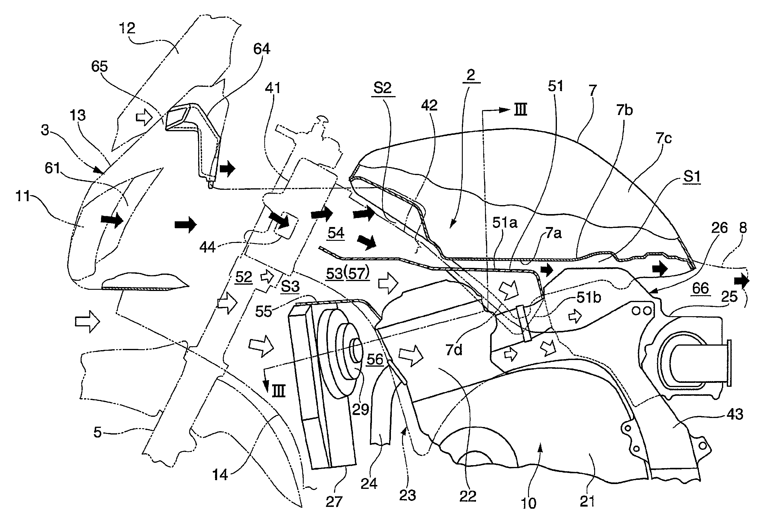
The present invention aims to address the heat evacuation problem of a motorcycle by designing a cooling structure for the vehicle body. The structure includes a heat blocking member that covers the upper part of the engine, which separates the cooling air passage into an engine side and a fuel tank side. The cooling air passage is designed to improve heat evacuation efficiency during both operating conditions of the motorcycle.

Problems solved by technology

In such constructions, however, the airflow is created by forward movement of the vehicle and a slow moving vehicle will not generate sufficient airflow to adequately reduce the impact of engine heat on the fuel tank.
In addition, relatively high-temperature air in the engine region sometimes rises due to a negative pressure region created behind a wind screen during normal operating speeds, especially at highway speeds.

Method used


Image

  • Vehicle body cooling structure for motorcycle and motorcycle
  • Vehicle body cooling structure for motorcycle and motorcycle
  • Vehicle body cooling structure for motorcycle and motorcycle

Examples


Embodiment Construction

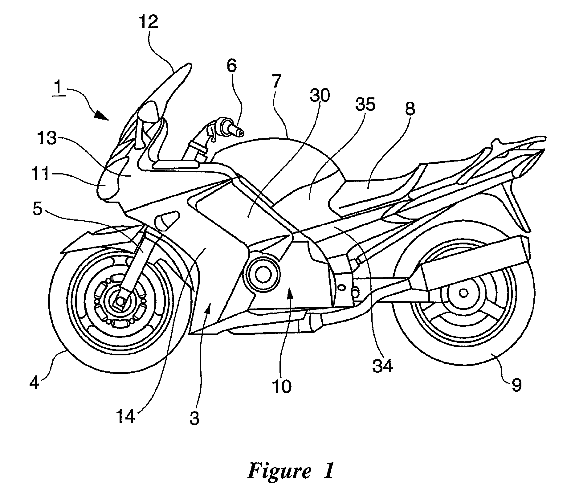
[0029]FIG. 1 is a side view of a motorcycle 1 comprising a cooling structure for a vehicle body that is arranged and configured in accordance with certain features, aspects and advantages of the present invention. The motorcycle 1 comprises a vehicle body cooling structure 2 (see FIG. 2). The motorcycle 1 can be an on-road-type motorcycle comprising a cowling 3 that covers a forward region of the vehicle body. In FIG. 1, a front wheel 4, a front fork5, steering handlebars 6, a fuel tank 7, a seat 8, a rear wheel 9, and an engine 10 are shown. These components can be arranged and configured in any suitable manner.

[0030]With reference to FIGS. 4 through 6, the illustrated cowling 3 comprises a front cowling 13 that generally surrounds a pair of left and right head lights 11, 11 and that has a wind screen 12 (see FIGS. 1 and 2), a pair of left and right side cowlings 14, 14 extending downward from the lower end of the front cowling 13, and other components. One or more of these compone...


PUM


Abstract

A vehicle body cooling structure for a motorcycle comprises a cooling air passage that extends between an engine and a fuel tank in the front-and-rear direction. A cowling covers the front part of the vehicle body, which contains the engine. The vehicle body cooling structure also comprises a heat blocking member that covers an upper part of the engine. The cooling air passage is separated into an engine side cooling air passage and a fuel tank side cooling air passage by the heat blocking member.

Description

CROSS-REFERENCE TO RELATED APPLICATIONS[0001]This application claims the priority benefit of Japanese Patent Application No. 2005-253512, filed Sep. 1, 2005, which is hereby incorporated by reference in its entirety.BACKGROUND OF THE INVENTION[0002]1. Field of the Invention[0003]The present application generally relates to a motorcycle and a vehicle body cooling structure for a motorcycle that redirects into a space between an engine and a fuel tank airflow created during forward movement of the vehicle.[0004]2. Description of the Related Art[0005]Motorcycles can feature a cowling that covers the front part of the vehicle body. Some of these cowlings include a ventilating structure that directs airflow created during movement of the motorcycle to the inside of the cowling. The ventilating structure directs the airflow between the engine and the fuel tank and other components inside the cowling. The airflow sweeps the air heated by the engine out of the region of the fuel tank. Thus,...

Claims


Application Information

Patent Timeline
Patent Type & Authority Patents(United States)
IPC IPC(8): B62K11/00B62M7/02B62J99/00
CPCB62J99/00B62K11/04B62M7/02F02M35/10268F02M35/162F02M35/10262Y02T10/146Y02T10/12B62J41/00
Inventor IWANAGA, SADAMU
Owner YAMAHA MOTOR CO LTD
Learn More