
Pressure sensor equipped with pressure sensing diaphragm

a diaphragm and pressure sensor technology, applied in the direction of rapid change measurement, fluid pressure measurement using elastically deformable gauges, instruments, etc., can solve the problems of diaphragm flexion decrease and pressure sensor sensitivity decrease, so as to minimize the loss of transmitting pressure, reduce the thickness, and minimize the effect of transmission

Inactive Publication Date: 2009-07-07
DENSO CORP
View PDF19 Cites 15 Cited by
  • Summary
  • Abstract
  • Description
  • Claims
  • Application Information

AI Technical Summary

Benefits of technology

[0012]It is another object of the invention to provide a pressure sensor equipped with a pressure-sensing diaphragm which is designed to minimize the thermal distortion of the diaphragm without use of a cooling mechanism.
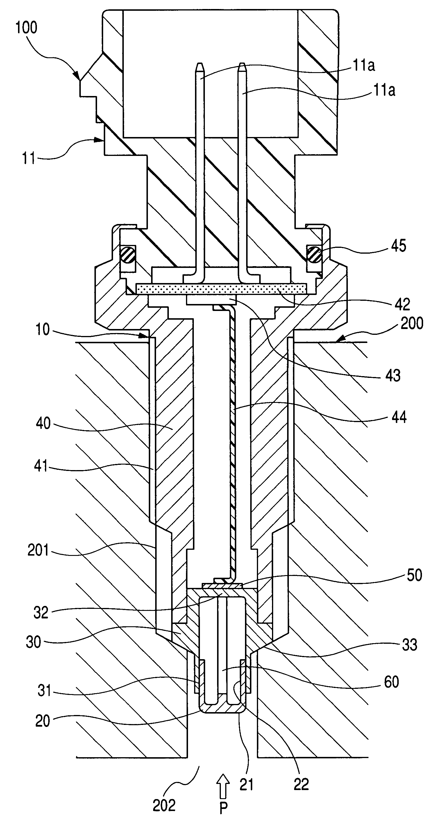
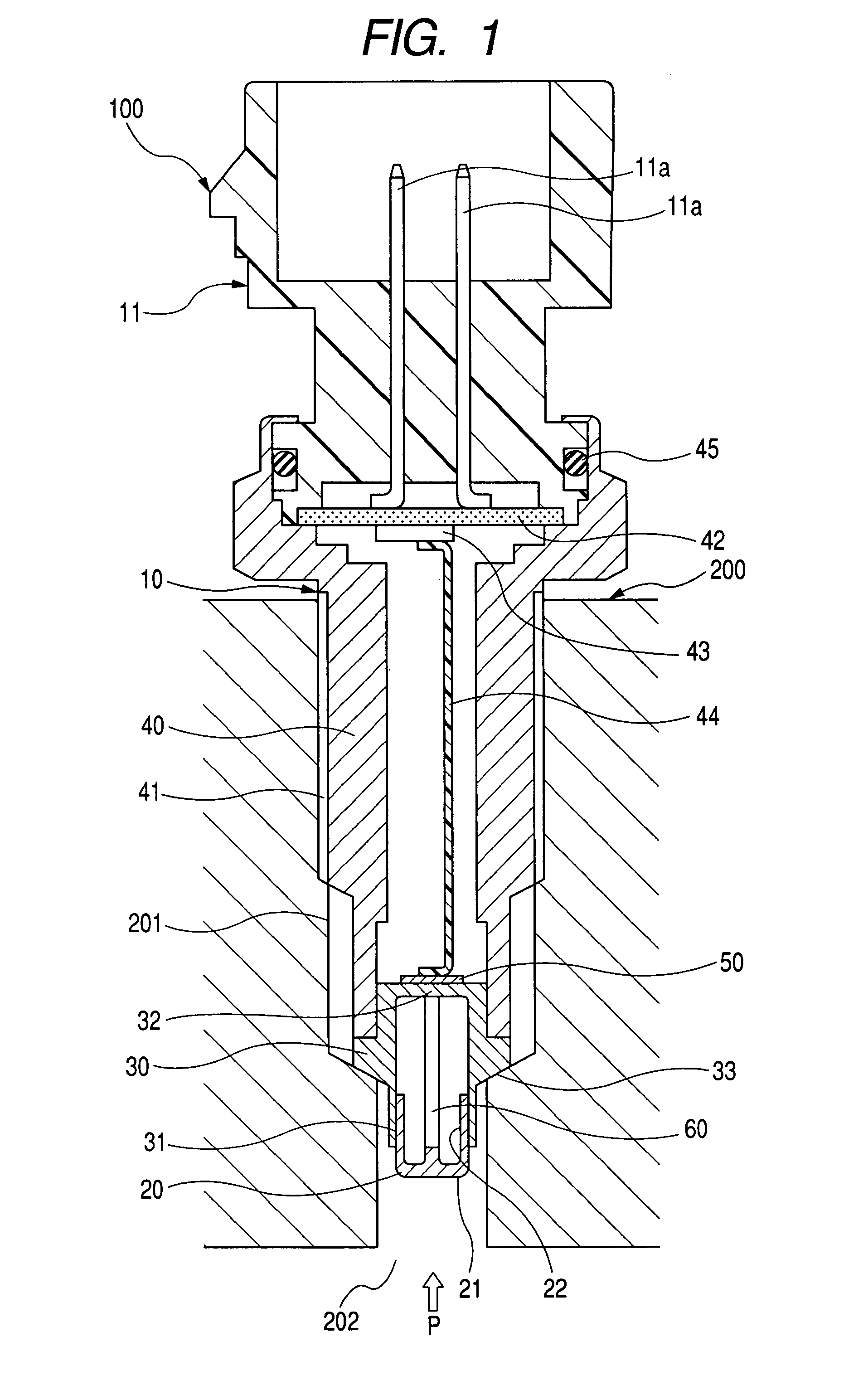
[0015]Specifically, the inclusion of the liquid in the closed chamber between the first and second diaphragms results in an increase in heat capacity of the diaphragm assembly to decrease the thermal distortion of the diaphragm assembly without sacrificing the sensitivity of the pressure sensor.
[0020]The first diaphragm may be lower in spring constant than the second diaphragm to absorb a change in volume of the liquid arising from, for example, thermal expansion thereof to minimize transmission thereof to the second diaphragm.
[0022]The closed chamber has a thickness in a thickness-wise direction of the diaphragm assembly. The thickness of the closed chamber is smaller than a distance between ends of the closed chamber in a radius direction of the diaphragm assembly, thereby minimizing the loss in transmitting the pressure to the pressure transmitting member.
[0028]The first diaphragm may be lower in spring constant than the second diaphragm to absorb a change in volume of the gel to minimize transmission thereof to the second diaphragm. This is achieved by designing the first diaphragm to be smaller in thickness than the second diaphragm or have a deformable area smaller in diameter than a deformable area of the second diaphragm.
[0029]The closed chamber has a thickness in a thickness-wise direction the diaphragm assembly. The thickness of the closed chamber is smaller than a distance between ends of the closed chamber in a radius direction of the diaphragm assembly, thereby minimizing the loss in transmitting the pressure to the pressure transmitting member.

Problems solved by technology

This, however, results in a decrease in flexion of the diaphragm when exposed to the pressure, which leads to a decrease in sensitivity of the pressure sensor.

Method used


Image

  • Pressure sensor equipped with pressure sensing diaphragm
  • Pressure sensor equipped with pressure sensing diaphragm
  • Pressure sensor equipped with pressure sensing diaphragm

Examples


second embodiment

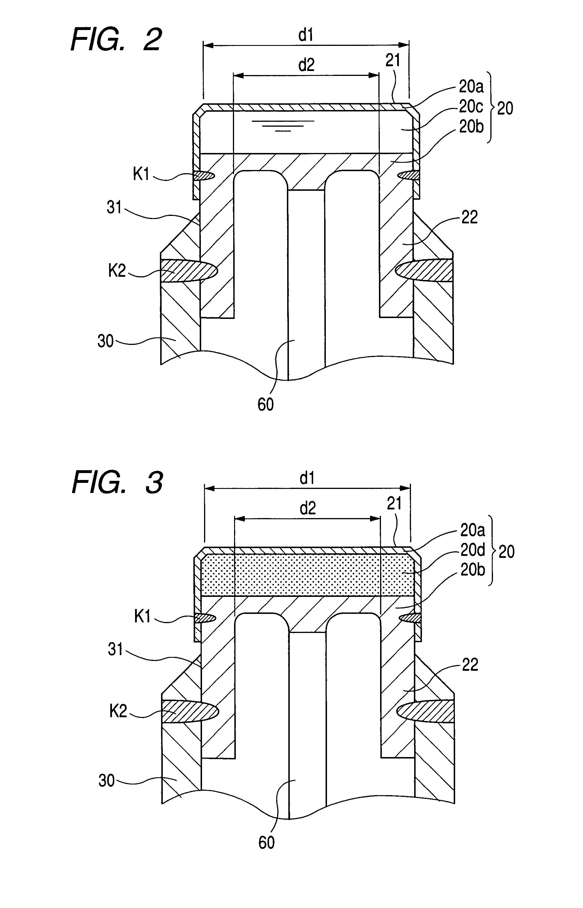
[0071]FIG. 3 is a partially longitudinal sectional view which shows the pressure sensor 100 according to the invention.

[0072]The diaphragm assembly 20 is made up of the first diaphragm 20a, the second diaphragm 20b, and a layer of gel 20d disposed in the chamber, like the first embodiment, between the first and second diaphragms 20a and 20b. The joining between the first and second diaphragms 20a and 20b and between the metallic stem 30 and the second diaphragm 20b are achieved in the same manner as in the first embodiment.

[0073]The gel 20d is, for example, fluoro gel, silicone gel, or phlorosilicone gel which is excellent in resistance to intense heat so that it resists decomposition when exposed to the heat as produced by combustion of the mixture in the engine 200.

first embodiment

[0074]The fabrication of the diaphragm assembly 20 is achieved in the same manner as in the first embodiment using the gel 20d instead of the oil 20c, and explanation thereof in detail will be omitted here.

[0075]When the combustion pressure P is exerted on the pressure-exposed surface 21 of the first diaphragm 20a, it is transferred to the second diaphragm 20b through the gel 20d, to the pressure transmitting bar 60, and to the flexible end 201 of the metallic stem 30. The pressure sensing device 50 is, like the first embodiment, sensitive to the pressure, as exerted on the flexible end 201, to output a signal indicative thereof.

[0076]The diaphragm assembly 20 is, like the first embodiment, designed to have the chamber between the first diaphragm 20a and the second diaphragm 20b filled with the gel 20d, thus resulting in an increase in thickness of the sensitive head of the diaphragm assembly 20 (i.e., a total thickness of the diaphragm assembly 20) as compared with the absence of t...


PUM

PropertyMeasurementUnit
thicknessaaaaaaaaaa
thicknessaaaaaaaaaa
thicknessaaaaaaaaaa

Abstract

A pressure sensor is provided which may be employed in measuring the combustion pressure in an internal combustion engine. The pressure sensor is equipped with a pressure sensing diaphragm assembly which includes a first diaphragm, a second diaphragm, and liquid or gel. The first diaphragm is flexible when exposed to pressure to be measured and joined to the second diaphragm to define a closed chamber filled with the liquid or gel to transmit the pressure to the second diaphragm. A pressure transmitting member is disposed in abutment with the second diaphragm to transmit the pressure, as transmitted from the first diaphragm, to a pressure sensing device. The inclusion of the liquid or gel in the closed chamber between the first and second diaphragms results in an increase in heat capacity of the diaphragm assembly to decrease the thermal distortion thereof without sacrificing the sensitivity of the pressure sensor.

Description

CROSS REFERENCE TO RELATED DOCUMENT[0001]The present application claims the benefit of Japanese Patent Application No. 2006-247950 filed on Sep. 13, 2006, the disclosure of which is incorporated herein by reference.BACKGROUND OF THE INVENTION[0002]1. Technical Field of the Invention[0003]The present invention relates generally to an improved structure of a pressure sensor equipped with a pressure-sensing diaphragm to be exposed to pressure, for example, produced by combustion of fuel in an automotive internal combustion engine.[0004]2. Background Art[0005]There have been proposed pressure sensors which include a casing, a pressure-sensing diaphragm fitted in an end of the casing, and a pressure transmitting member disposed inside the casing. For example, Japanese Patent First Publication No. 2004-347387 and U.S. Pat. No. 5,471,883 disclose such a type of pressure sensors designed to measure the pressure in a cylinder of an automotive engine. The pressure-sensing diaphragm has an out...

Claims


Application Information

Patent Timeline
Patent Type & Authority Patents(United States)
IPC IPC(8): G01L7/08
CPCG01L9/0054G01L23/18G01L19/0046
Inventor TOYODA, INAO
Owner DENSO CORP
Learn More