
Ignition device for an internal combustion engine and method for its operation

a technology of internal combustion engine and ignition device, which is applied in the direction of automatic control of ignition, machines/engines, mechanical equipment, etc., can solve the problems of cylinder thermal stress to a greater extent, troublesome ignition module as well as engine speed sensor, and inability to adjust the ignition timing constructively, so as to achieve the effect of precise ignition and simplified ignition devi

Active Publication Date: 2009-06-30
ANDREAS STIHL AG & CO KG
View PDF9 Cites 9 Cited by
  • Summary
  • Abstract
  • Description
  • Claims
  • Application Information

AI Technical Summary

Benefits of technology

[0009]By eliminating the angle-of-rotation sensor for recognizing the actual mechanical crankshaft angle position, the mechanical configuration of the ignition device itself is simplified; this also leads to a more precise ignition action because mechanical tolerance errors resulting during assembly of an angle-of-rotation sensor are no longer present. Each system of a produced series calibrates itself in operation so that, for example, in mass production of hand-held power tools, each individually produced device works optimally as a result of self-calibration.
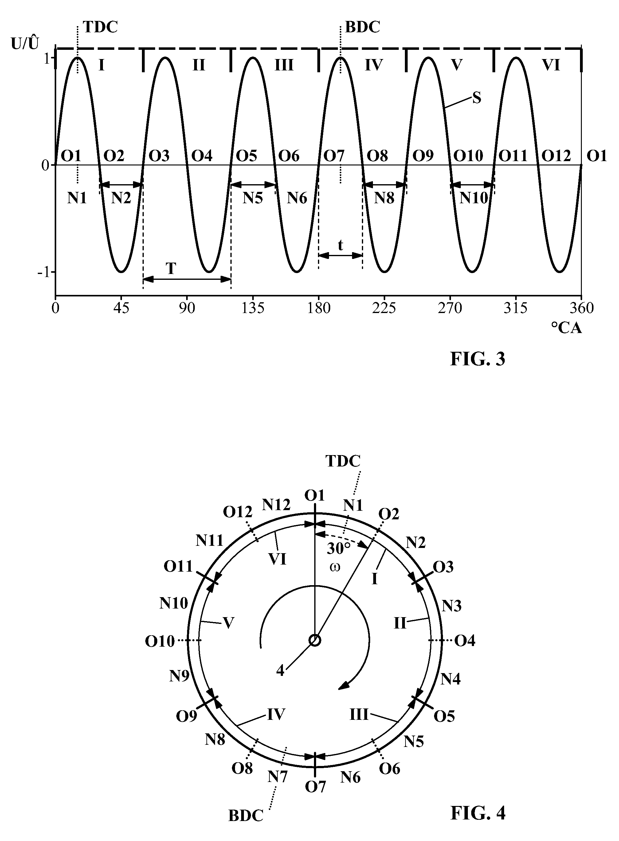
[0014]For simplifying locking of the alternating voltage signal on the mechanical crankshaft angle position, advantageously the rotational position of the alternating current generator on the machine unit and the top dead center of the piston are adjusted relative to one another such that a zero crossing interval is symmetrically positioned to the top dead center of the piston. Expediently, the adjustment is such that a zero crossing of the induced alternating voltage signal is preferably approximately 15° CA before top dead center of the piston. In this way, it is also achieved that, when starting the internal combustion engine, a branch of the half wave can be used as a voltage supply for the electronics so that the system is operational during start of the engine at an early point in time even without a battery. This provides for beneficial starting conditions. The adjustment can also be done such that the course of minimal engine speed is within the average value. In this way, a minimal interval engine speed can be determined in a simple way that provides as a significant feature the top dead center of the piston. It can be expedient to differentiate the engine speed course of the interval engine speed, i.e. the angle information signal; in this way, the differential curve exhibits distinct hooks that can be correlated to a characteristic mechanical crankshaft angle position, for example, the top dead center of the piston.
[0017]When electric consumers are operated at the alternator, it is advantageous for an unequivocal position determination of a zero crossing of the voltage signal to stop or interrupt current flow by a connected electrical load at the time when the zero crossing occurs. In this way, signal displacements caused by inductivity or capacitance are safely prevented. It was found to be advantageous to stop or interrupt current flow, e.g. by switching off, in the angle range of from approximately 5 ° CA before zero crossing to approximately 1° CA after zero crossing.
[0018]The ignition unit is comprised advantageously of a control unit such as a microprocessor or the like as well as a high-voltage unit as a separate unit from the control unit. In this way, the control unit can be arranged separate from the high-voltage unit in a thermally advantageous area of the power tool. Expediently, an arrangement on or near a component of the motor unit is provided. For example, the control unit can be arranged at the mixture processing device such as a carburetor. The motor unit is expediently connected together with the carburetor by means of antivibration elements to the housing of the power tool wherein the carburetor advantageously is connected by means of an elastic channel resiliently to the internal combustion engine. An arrangement of the control unit on the carburetor housing has the advantage of vibration decoupling because the carburetor is decoupled by means of antivibration elements from the housing and, because of the elastic connection to the internal combustion engine, is therefore vibration decoupled from it. In this way, a vibration decoupled arrangement of the electronic control unit is achieved without the electric connecting lines to the high-voltage unit or to the alternator having to be extended across the antivibration gap. A thermally beneficial arrangement is provided that is also vibration-resistant and soiling-resistant.

Problems solved by technology

The ignition trigger must be attached circumferentially relative a revolving pole wheel on the crankcase in a precise rotational position wherein, in mass production of such engines, fluctuations with regard to mechanical arrangement of the ignition trigger occur that can impair ignition timing.
Moreover, the constructively fixed arrangement of the ignition generator, ignition module as well as engine speed sensor is troublesome because these parts are often arranged within the cooling air passage at the fan wheel and occupy space in the cooling air passage.
This can cause cooling problems so that the cylinder is thermally stressed to a greater extent.

Method used


Image

  • Ignition device for an internal combustion engine and method for its operation
  • Ignition device for an internal combustion engine and method for its operation
  • Ignition device for an internal combustion engine and method for its operation

Examples


Embodiment Construction

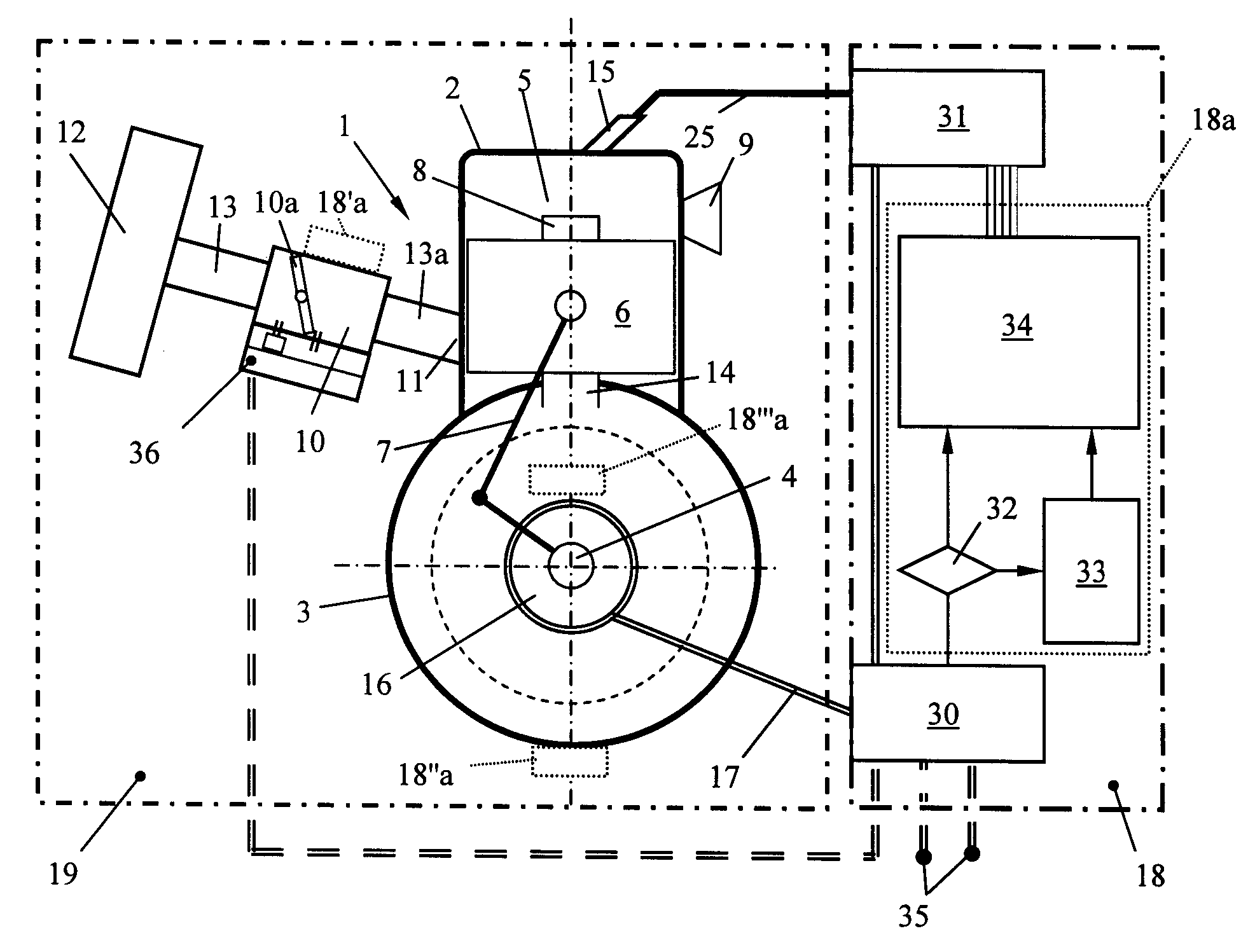
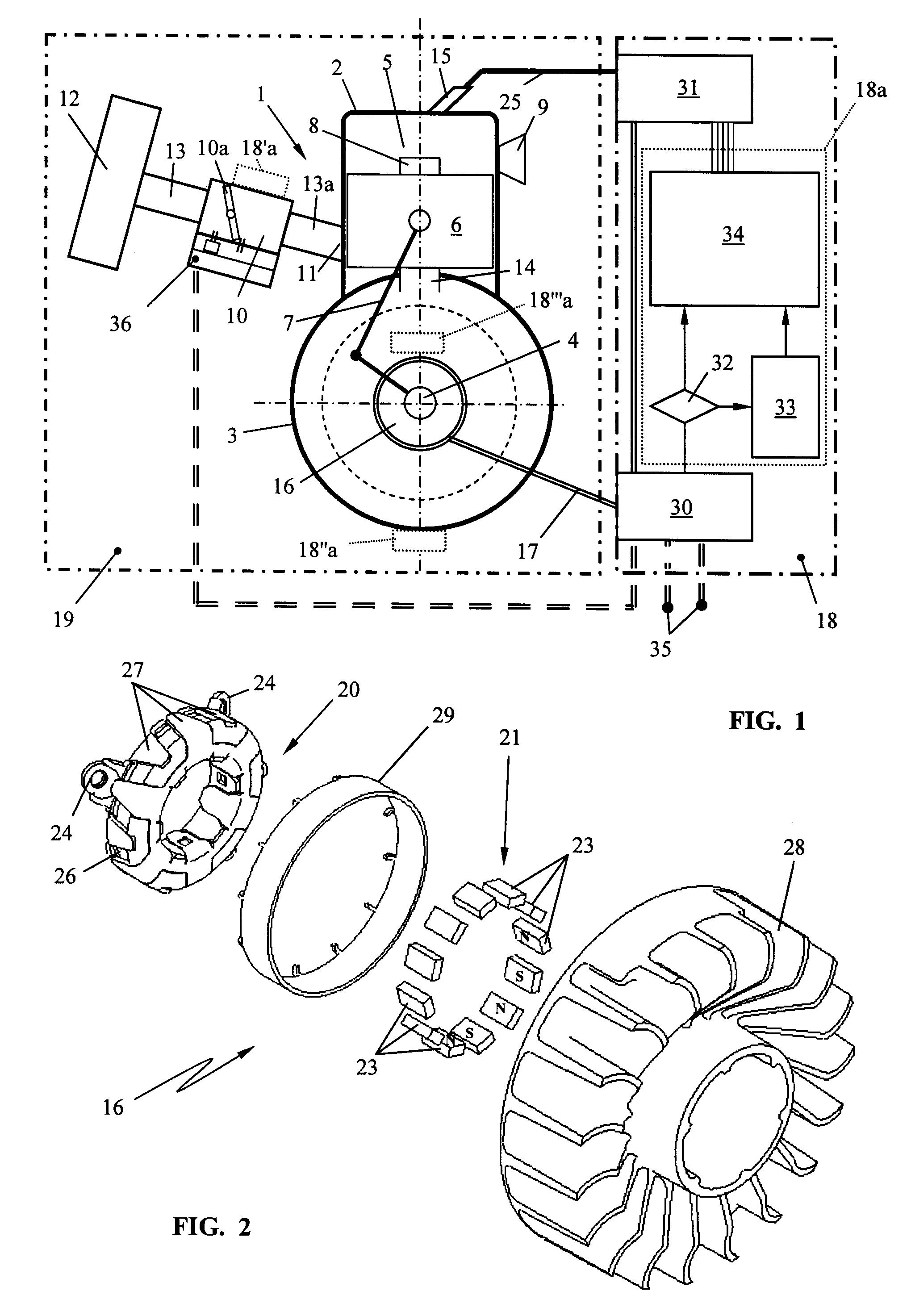
[0034]The schematic illustration of FIG. 1 shows the motor unit 19 with an internal combustion engine 1 configured in particular as a two-stroke engine. The ignition device according to the invention is not limited to utilization in connection with single-cylinder or multi-cylinder two-stroke engines; it is also utilizable in connection with single-cylinder or multi-cylinder four-stroke engines or similar engines, in particular, reciprocating piston engines.

[0035]The internal combustion engine 1 of the motor unit 19 comprises a cylinder 2 with crankcase 3 in which a crankshaft 4 is rotatably supported. In the cylinder 2 a combustion chamber 5 is provided that is delimited by the reciprocating piston 6. The piston 6 is connected by means of connecting rod 7 to the crankshaft 4 in the crankcase 3 and drives the crankshaft 4 in rotation. In the illustrated embodiment, an intake port 8 for the combustion air and / or fuel / air mixture opens into the combustion chamber 5 wherein the intake ...


PUM


Abstract

An ignition device for a motor unit with an internal combustion engine provided with a piston, a combustion chamber with a spark plug, a crankshaft driven by the piston, an intake port supplying combustion air to the combustion chamber, an exhaust for removing combustion gases from the combustion chamber, a signal generator driven by the crankshaft and emitting for one crankshaft revolution an alternating voltage signal, has an ignition unit that triggers a spark at the spark plug at a preselectable timing. The ignition unit is a module separate from the motor unit. An alternating voltage signal generated by the signal generator is supplied to the ignition unit as an information signal sufficient for operating the internal combustion engine. The alternating voltage signal is supplied to a first unit for energy processing and to a second unit for processing information for control of the internal combustion engine.

Description

BACKGROUND OF THE INVENTION[0001]The invention relates to an ignition device for a motor unit comprising an internal combustion engine, in particular for a motor unit with a two-stroke engine of a portable hand-held power tool. The internal combustion engine of the motor unit comprises a piston, a combustion chamber with a spark plug, a crankshaft that is driven in rotation by the piston, an intake port for supplying combustion air into the combustion chamber, an exhaust for removing combustion gases from the combustion chamber, as well as a signal generator driven in rotation by the crankshaft and attached to the motor unit and emitting for one crankshaft revolution sequential alternating voltage signals to an ignition unit that triggers a spark at the spark plug at a preselectable timing.[0002]Modern internal combustion engines as they are used in connection with hand-held portable power tools such as motor chain saws, trimmers, cut-off machines, blowers or similar devices are con...

Claims


Application Information

Patent Timeline
Patent Type & Authority Patents(United States)
IPC IPC(8): F02P5/06F02P5/00
CPCF02P1/04F02P7/0775
Inventor MAIER, GEORGLAYHER, WOLFGANGNEUMAIER, THOMASSCHIEBER, EBERHARDABOU-ALY, MOHAMED
Owner ANDREAS STIHL AG & CO KG
Learn More