
Systems and method for selectively controlling a state of hydration of a magnetic data storage medium

a data storage medium and selective control technology, applied in the field of data storage systems, can solve the problems of forming metallic bridges on the head, prone to failure of read sensors, and forming metallic bridges via electrostatic or electrochemical interaction between the head and the tap

Inactive Publication Date: 2009-06-23
IBM CORP
View PDF12 Cites 17 Cited by
  • Summary
  • Abstract
  • Description
  • Claims
  • Application Information

AI Technical Summary

Benefits of technology

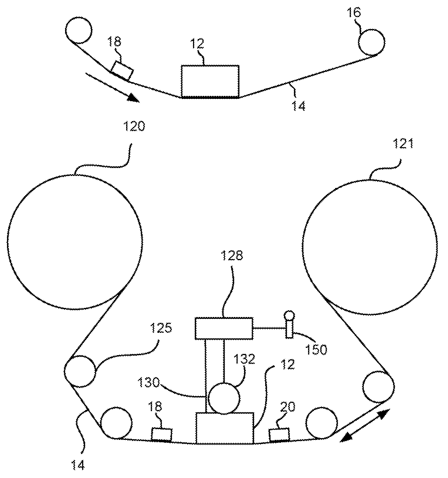
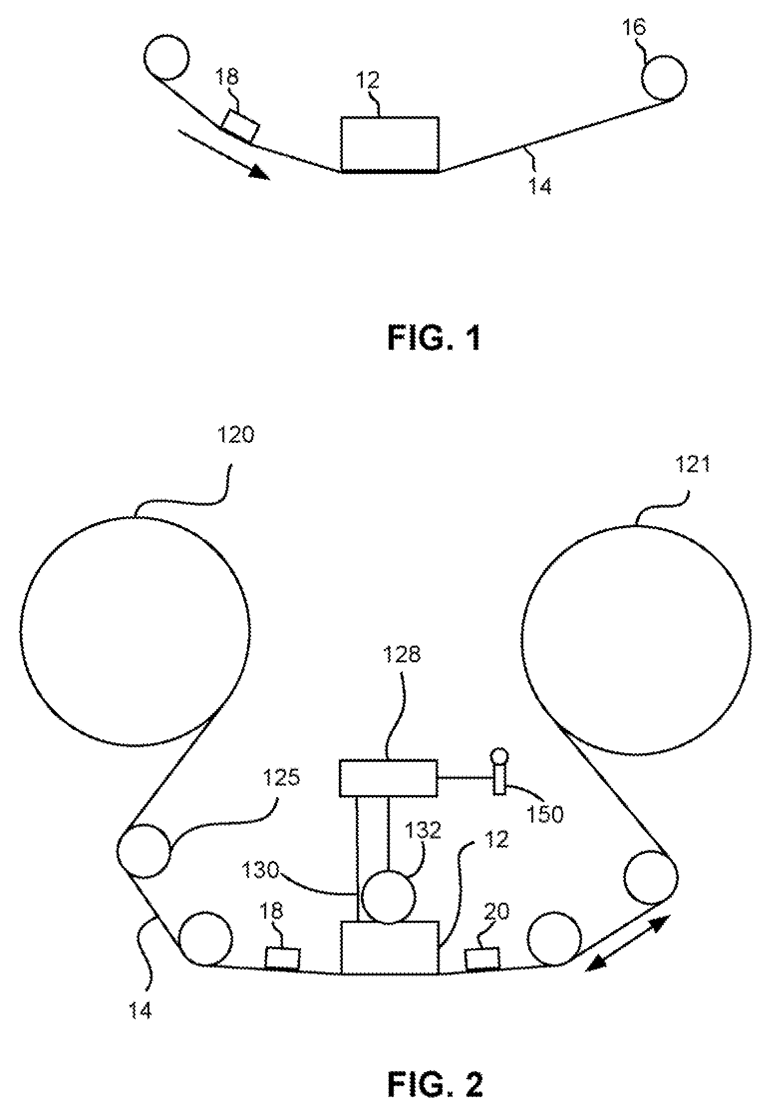
The patent describes a magnetic storage system that includes a magnetic head for reading and writing to a magnetic medium. The system also has a drive mechanism to move the medium over the head. The system has a first element that can selectively alter the voltage of the medium to change its hydration state. This element can be in contact with the medium before it passes over the head. The voltage applied to the medium is based on the voltage of the medium and the ambient humidity level. The patent also describes a tape drive system with a magnetic head and a controller that can apply a voltage to the tape to change its hydration state. The technical effect of this patent is to provide a system for controlling the hydration state of a magnetic medium or tape, which can improve the performance and reliability of magnetic storage devices.

Problems solved by technology

One problem frequently encountered during reading and writing to tape is that magnetic materials or fragments therefrom can come loose from the tape and adhere to the head, sometimes leading to the formation of metallic bridges on the head.
Another problem is formation of metallic bridges via electrostatic or electrochemical interaction between head and tape.
Read sensors are particularly susceptible to failure due to shield-shorting as a result of bridging.
However, at the other extreme, operating in a high humidity environment, e.g., typically greater than about 55% relative humidity, is problematic in that the tape may become too hydrated.
This water in turn is implicated in corrosion of corrodible materials in the head, such as the iron in the writer pole tips.
In addition, aluminum oxide, which is a typical component in modern heads, is amphitheric and susceptible to chemical attack when subjected to a hydrated environment.
It is found that excessive tape hydration accelerates head erosion.
Further, excessive hydration is widely believed to increase stiction between the tape and the head.
In the former case, such a recessed sensor has not been implemented and is believed to be difficult to manufacture, and would also result in an undesirable spacing loss.
The latter method is complex and expensive and the coatings may wear off over time, even with pre-recession.

Method used


Image

  • Systems and method for selectively controlling a state of hydration of a magnetic data storage medium
  • Systems and method for selectively controlling a state of hydration of a magnetic data storage medium

Examples


example 1

[0044]A first element is positioned in front of a tape head with respect to the direction of tape travel across the head. A second element is positioned on an opposite side of the tape head relative to the first element. The substrate of the head is biased at 1.5V.

[0045]Humidity is measured at about 55% relative humidity. The system determines that the tape voltage should initially be about 2V to achieve a tape hydration level that does not promote head corrosion but is not so low that parasitic accumulations are conductive. A voltage is applied by the first element at a level sufficient to provide a reading at the second element of about 2V. An illustrative voltage level applied at the first element may be about 3-7V.

example 2

[0046]A first element is positioned in front of a tape head with respect to the direction of tape travel across the head. A second element is positioned on an opposite side of the tape head relative to the first element. The substrate of the head is biased at 1.5V

[0047]Humidity is measured at about 75% relative humidity. The system determines that the tape voltage should initially be about 2V to achieve a tape hydration level that does not promote head corrosion but is not so low that parasitic accumulations are conductive. A voltage is applied by the first element at a level sufficient to provide a reading at the second element of about 2V. An illustrative voltage level applied by the first element may be about 5-10V.

example 3

[0048]A first element is positioned in front of a tape head with respect to the direction of tape travel across the head. A second element is positioned on an opposite side of the tape head relative to the first element. The substrate of the head is biased at 1.5V.

[0049]Humidity is measured at about 40% relative humidity. The system determines that the tape voltage should be about 1.0 to 1.5V to match the head substrate voltage. A voltage is applied by the first element at a level sufficient to provide a reading at the second element of about 1.0-1.5V. An illustrative voltage level applied at the first element may be about 0-1.5V.


PUM

PropertyMeasurementUnit
wrap anglesaaaaaaaaaa
voltageaaaaaaaaaa
voltageaaaaaaaaaa

Abstract

A magnetic storage system according to one embodiment includes a magnetic head adapted for at least one of reading from a magnetic medium and writing to the medium; a drive mechanism for directing the medium over the head; and a first element for selectively altering a voltage of the medium for altering a state of hydration of the medium.

Description

FIELD OF THE INVENTION[0001]The present invention relates to data storage systems, and more particularly, this invention relates to a system for selectively altering the hydration of a magnetic data storage medium.BACKGROUND OF THE INVENTION[0002]Business, science and entertainment applications depend upon computers to process and record data, often with large volumes of the data being stored or transferred to nonvolatile storage media, such as magnetic discs, magnetic tape cartridges, optical disk cartridges, floppy diskettes, or floptical diskettes. Typically, magnetic tape is the most economical means of storing or archiving the data. Storage technology is continually pushed to increase storage capacity and storage reliability. Improvement in data storage densities in magnetic storage media, for example, has resulted from improved medium materials, improved error correction techniques and decreased areal bit sizes. The data capacity of half-inch magnetic tape, for example, is now...

Claims


Application Information

Patent Timeline
Patent Type & Authority Patents(United States)
IPC IPC(8): G11B15/18G11B5/10G11B5/76
CPCG11B5/40G11B33/1453
Inventor BISKEBORN, ROBERT GLENNLO, CALVIN SHYHJONG
Owner IBM CORP
Learn More