
Modular window well and associated accessories

a module and window well technology, applied in the field of window wells, can solve the problems of large unitary window wells that are not easily adjustable in height, cumbersome transportation, maneuvering and installation, and limited design life, and achieve the effect of effectively adjusting the ladder and convenient interfavorability

Active Publication Date: 2009-06-23
WATKINS DONALD J
View PDF15 Cites 6 Cited by
  • Summary
  • Abstract
  • Description
  • Claims
  • Application Information

AI Technical Summary

Benefits of technology

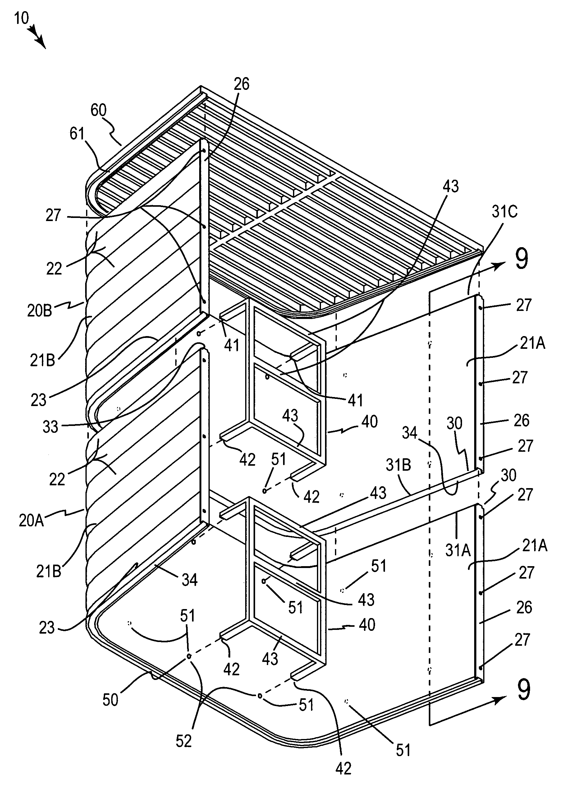
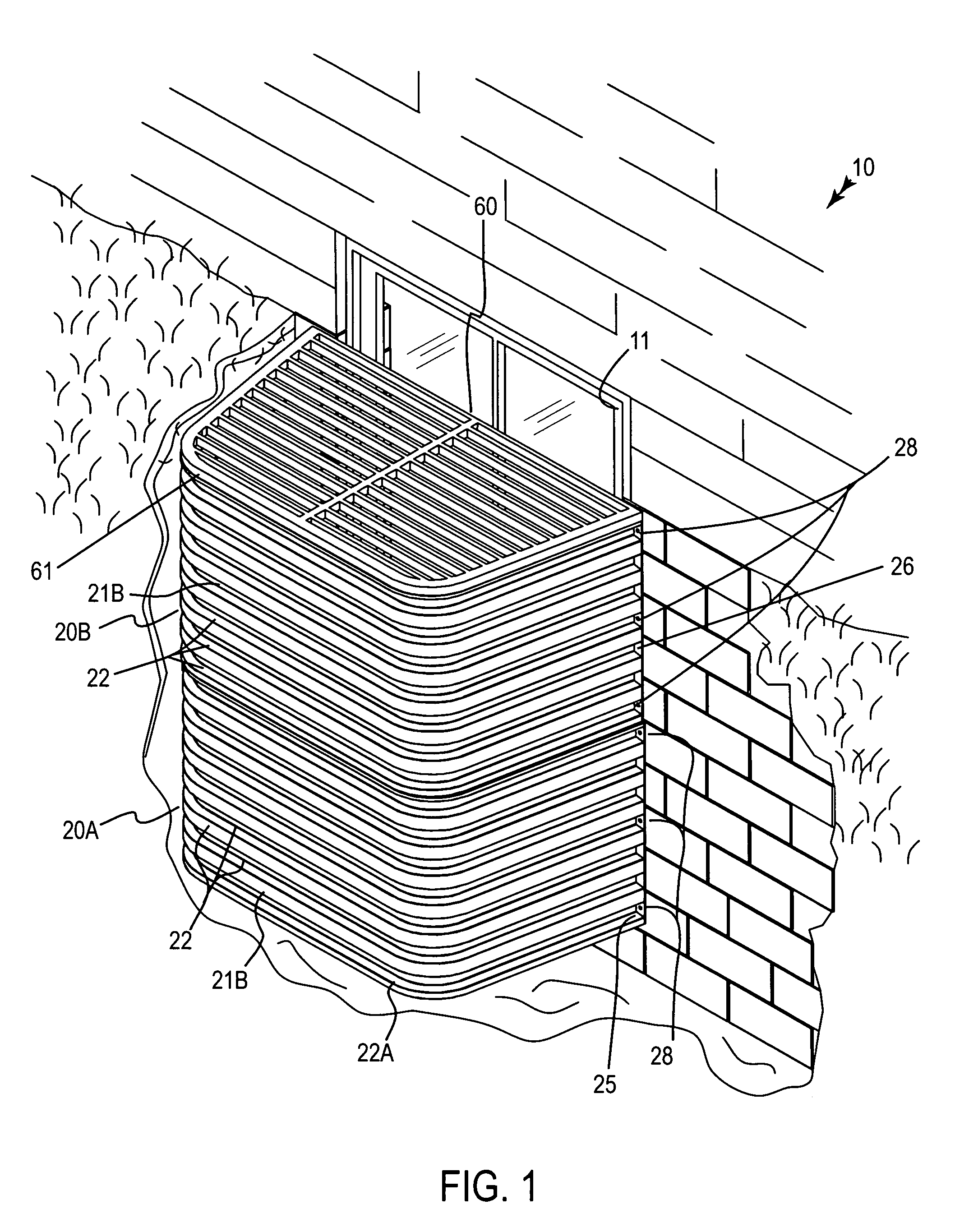
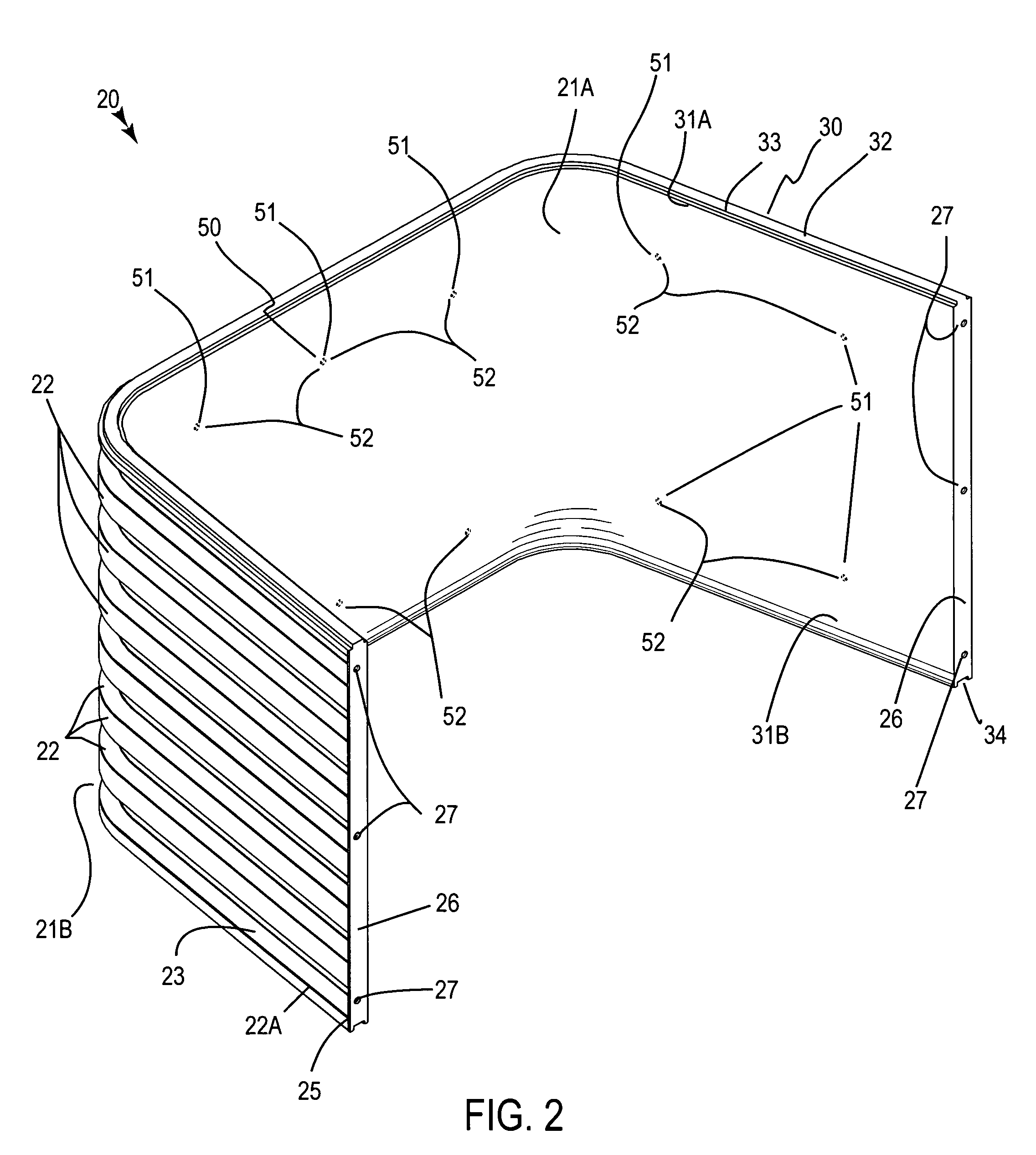
[0012]The window well assembly includes a plurality of U-shaped walls that have smooth interior surfaces and corrugated exterior surfaces respectively. Such U-shaped walls are formed from deformably resilient polyvinyl material such that the exterior surfaces can conveniently be resiliently biased from a vertical plane and thereby effectively be adapted to a stressed position for fitting within confined subterranean regions surrounding the foundation window wall. The U-shaped walls further have a plurality of coextensively shaped and compressible ribs that are equidistantly juxtaposed along an entire surface area of the exterior surfaces respectively. Such ribs are resiliently compressible along a horizontal plane such that the U-shaped walls can advantageously absorb an impact force without dislodging from a stacked position.
[0013]Each of the U-shaped walls is provided with an end wall that has an opening formed therein for effectively allowing the ribs to freely compress and expand. Such openings are spaced at opposed ends of selected ones of the ribs respectively. Each of the U-shaped walls preferably has oppositely disposed ends provided with a plurality of apertures for effectively receiving a plurality of fasteners therethrough so that the U-shaped walls can advantageously be securely connected directly to an outer perimeter of the foundation window wall.
[0015]A plurality of ladders are directly seated against the interior surfaces of the U-shaped walls for advantageously and conveniently assisting a user to climb up and over the U-shaped walls during exiting procedures.
[0016]A mechanism is included for snapping-on the ladders directly to the interior surfaces of the U-shaped walls such that each of the ladders can conveniently be independently and simultaneously detached from a corresponding one of the U-shaped walls as desired by the user. Such a ladder snap-on mechanism may include a plurality of recessed apertures formed directly in the interior surfaces of the U-shaped walls. The apertures include a plurality of aperture pairs that have a fixed spatial relationship corresponding to a width of the ladders respectively. Such ladders have top and bottom ridges laterally spaced from associated rungs thereof so that the top and bottom ridges become directly nested within associated ones of the aperture pairs respectively. Each ladder is coextensively shaped and conveniently interfittable in alternate ones of the aperture pairs so that the user can advantageously and effectively configure the ladders in alternate patterns and along alternate planes.

Problems solved by technology

The considerable size of the window wells make them cumbersome to transport, maneuver and install.
Such large unitary window wells are also not easily adjustable in height which is not desirable when the windows are located at varying depths with respect to a ground surface.
Furthermore, due to the metal composition thereof, early window well designs have a limited lifespan since the structure is vulnerable to oxidative processes, like rust, which greatly reduces the structural rigidity thereof.
Such a separate ladder, however, means that the user must expend more funds for the purchase thereof.

Method used


Image

  • Modular window well and associated accessories
  • Modular window well and associated accessories
  • Modular window well and associated accessories

Examples


Embodiment Construction

[0031]The present invention will now be described more fully hereinafter with reference to the accompanying drawings, in which a preferred embodiment of the invention is shown. This invention may, however, be embodied in many different forms and should not be construed as limited to the embodiment set forth herein. Rather, this embodiment is provided so that this application will be thorough and complete, and will fully convey the true scope of the invention to those skilled in the art. Like numbers refer to like elements throughout the figures.

[0032]The assembly of this invention is referred to generally in FIGS. 1-10 by the reference numeral 10 and is intended to provide a modular window well and associated accessories. It should be understood that the assembly 10 may be used to protect many different types of windows and should not be limited in use to only protecting basement level windows.

[0033]Referring initially to FIGS. 1, 2, 3, 4, 5, 6, 7, 8, 9 and 10, the assembly 10 inclu...


PUM


Abstract

A window well assembly includes U-shaped walls that have smooth interior and corrugated exterior surfaces, and are formed from polyvinyl material. The walls have coextensive ribs juxtaposed along an exterior surface thereof that are compressible. Each wall has an end wall with an opening formed therein, allowing the ribs to compress and expand. The openings are spaced at opposed ends of selected ribs. A mechanism is included for stacking the walls wherein a top edge of one wall receives a bottom edge of another wall. Ladders are seated against the interior surfaces of the walls. A mechanism is included for snapping the ladders onto the wall interior surface. A safety grill is mounted on top of the second wall, having an outer edge extending along a top edge of the second wall, for prohibiting the user from stepping into a cavity defined between the walls and the foundation window wall.

Description

CROSS REFERENCE TO RELATED APPLICATIONS[0001]Not Applicable.STATEMENT REGARDING FEDERALLY SPONSORED RESEARCH OR DEVELOPMENT[0002]Not Applicable.REFERENCE TO A MICROFICHE APPENDIX[0003]Not Applicable.BACKGROUND OF THE INVENTION[0004]1. Technical Field[0005]This invention relates to window wells and, more particularly, to a modular window well and associated accessories for retaining soil at a window having a sill height lower than an adjacent ground elevation.[0006]2. Prior Art[0007]For many years sub-terrain window systems have been designed to allow light into basement areas in order to make the space more desirable, as well as to meet building code requirements. These window systems generally comprise a standard size or other window located, at least in part, below grade. Provided at the window location is a window well structure surrounding the outside window surface which acts, at least in part, to retain the earth at a predetermined distance away from the outer window surface. ...

Claims


Application Information

Patent Timeline
Patent Type & Authority Patents(United States)
IPC IPC(8): E06B5/02
CPCE04F17/06E06C9/02
Inventor WATKINS, DONALD J.
Owner WATKINS DONALD J
Learn More