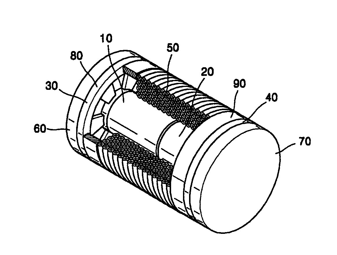
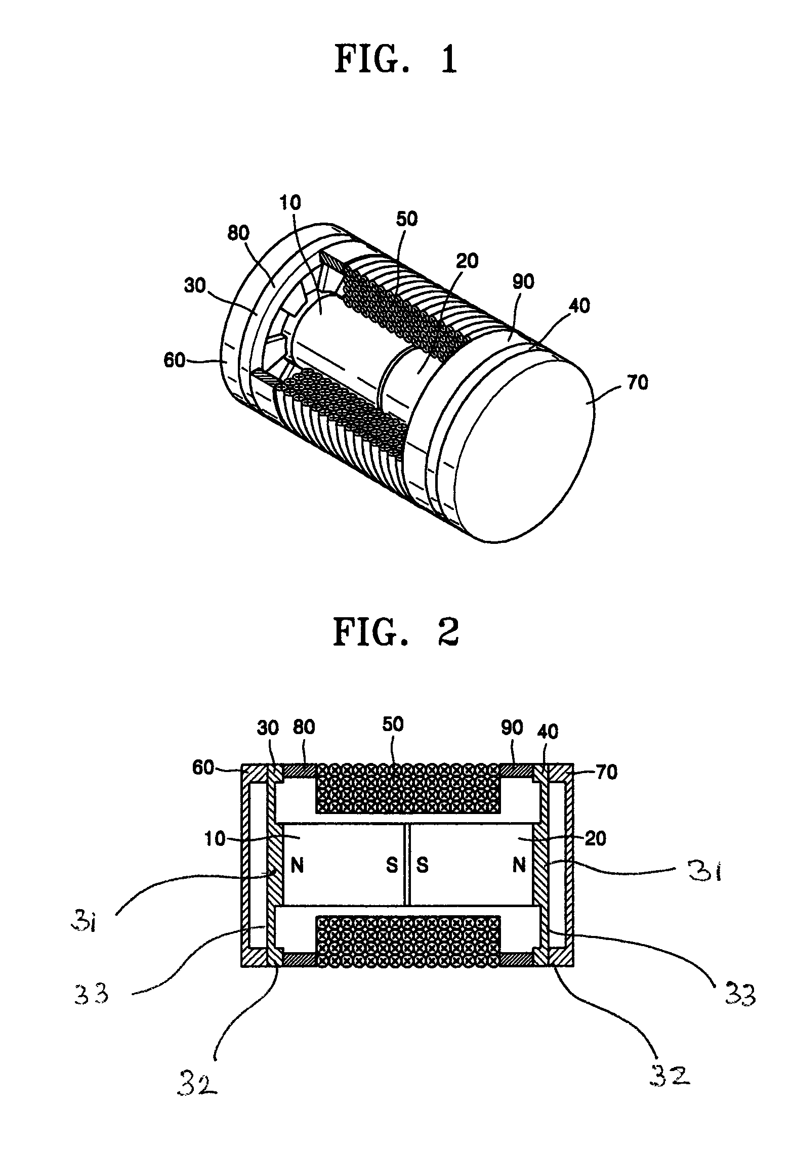
Middle ear implant transducer
a technology of implant transducers and middle ear, which is applied in the direction of electric transducers, deaf-aid sets, electrical equipment, etc., can solve the problems of generating severe distortion, generating distortion when the vibration characteristics of the transducer are different from those of the middle ear,
- Summary
- Abstract
- Description
- Claims
- Application Information
AI Technical Summary
Benefits of technology
Problems solved by technology
Method used
Image
Examples
first embodiment
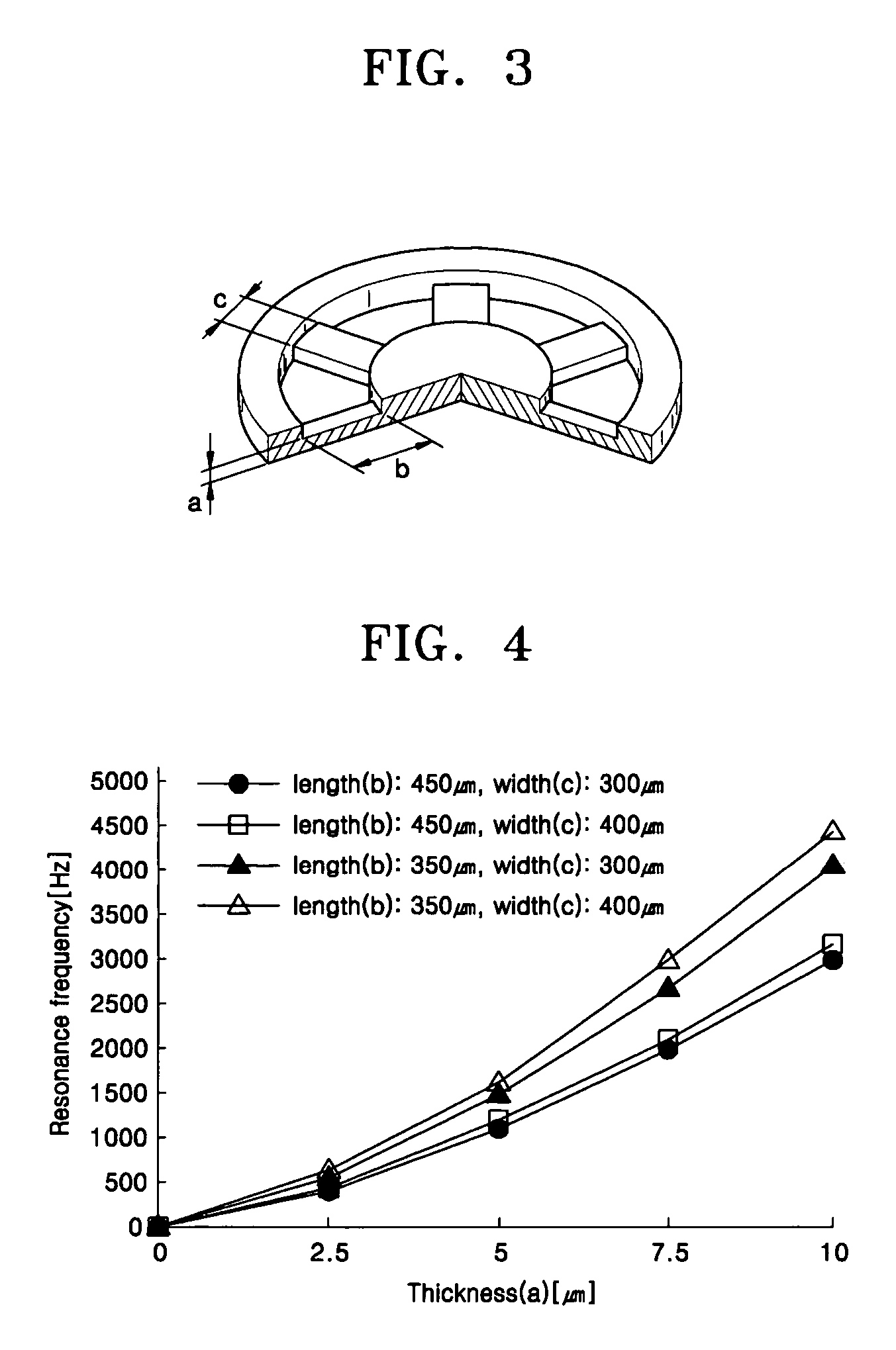
[0036]FIG. 5 is a perspective view of a vibrating member adapted to the middle ear implant transducer of FIG. 1 according to the present invention. Referring to FIG. 5, a vibrating member 130 includes a coupler 131 attached to first and second permanent magnets, a rim 132 attached to edges of first and second covers, and a support film 133 connecting the coupler 131 and the rim 132. The support film 133 includes a plurality of support film wings. In the present embodiment, the support film 133 includes four support film wings 133a, 133b, 133c, and 133d. However, the number of support film wings may be more or less, such as six or eight.
second embodiment
[0037]FIG. 6 is a perspective view of a vibrating member adapted to the middle ear implant transducer of FIG. 1 according to the present invention. Referring to FIG. 6, a vibrating member 230 includes a coupler 231 attached to first and second permanent magnets, a rim 232 attached to edges of first and second covers, and a support film 233 connecting the coupler 231 and the rim 232. The support film 233 includes a plurality of support film wings with widths that increase from the coupler 231 to the rim 232. In the present embodiment, the support film 233 includes four support film wings 233a, 233b, 233c, and 233d. However, the number of support film wings may be more or less, such as six or eight.
third embodiment
[0038]FIG. 7 is a perspective view of a vibrating member adapted to the middle ear implant transducer of FIG. 1 according to the present invention. Referring to FIG. 7, a vibrating member 330 includes a coupler 331 attached to first and second permanent magnets, a rim 332 attached to edges of first and second covers, and a support film 333 connecting the coupler 331 and the rim 332. The support film 333 is thinner than the coupler 331 and the rim 332. Accordingly, vibration of the coupler 331 is easily transmitted to the rim 332.
[0039]The support film may be composed of silicon. The support film can also be composed of polyimide.
[0040]A method of manufacturing a vibrating member adapted to a middle ear implant transducer of a hearing aid according to an embodiment of the present invention will now be described with reference to FIGS. 8 through 11.
[0041]Referring to FIG. 8, a silicon wafer 1 with both surfaces treated is prepared. The silicon wafer 1 is a crystalline silicon substrat...
PUM
| Property | Measurement | Unit |
|---|---|---|
| distance | aaaaa | aaaaa |
| constant widths | aaaaa | aaaaa |
| widths | aaaaa | aaaaa |
Abstract
Description
Claims
Application Information
 - R&D
- Intellectual Property
- Life Sciences
- Materials
- Tech Scout
- Unparalleled Data Quality
- Higher Quality Content
- 60% Fewer Hallucinations
Browse by: Latest US Patents, China's latest patents, Technical Efficacy Thesaurus, Application Domain, Technology Topic, Popular Technical Reports.
© 2025 PatSnap. All rights reserved.Legal|Privacy policy|Modern Slavery Act Transparency Statement|Sitemap|About US| Contact US: help@patsnap.com


