Eureka AIR delivers breakthrough ideas for toughest innovation challenges, trusted by R&D personnel around the world.

Method of installing prefabricated, segment concrete filled tube members

a technology of prefabricated segments and filled tubes, applied in the direction of bridges, bridge structural details, girders, etc., can solve the problems of difficult to fill concrete filled tube bridge girders with concrete at site, complicated work, and long work period, so as to shorten the work period

Active Publication Date: 2009-06-16
DAEWOO ENG & CONSTR CO LTD
View PDF22 Cites 12 Cited by
  • Summary
  • Abstract
  • Description
  • Claims
  • Application Information

AI Technical Summary

Benefits of technology

[0008]Accordingly, the present invention has been made to solve the above-mentioned problems occurring in the prior art, and an object of the present invention is to provide a fabrication structure capable of minimizing complicated in-site works to considerably shorten a term of works as compared with a cast-in-place concrete structure of the prior art.
[0009]Another object of the present invention is to provide a fabrication structure having greater rigidity for a vibration load or an axial load, as compared with a concrete structure of the prior art.
[0010]Still another object of the present invention is to provide a new constructing method that upon constructing a structure such as a bridge pier, prevents works at a high altitude to provide a safe, economical construction.

Problems solved by technology

However, since such concrete structures are constructed at in situ site, there are drawbacks in that works are very complicated and it takes a considerable term of works.
Generally concrete filled tube bridge girders are very difficult to be filled with concrete in tube at site.
So it's not efficient in bridge member.
In case of a high bridge pier, which may be executed as a concrete pillar by using a slip form method and the like, since it should be executed at a high altitude, works are risky and work efficiency becomes degraded.

Method used


Image

  • Method of installing prefabricated, segment concrete filled tube members
  • Method of installing prefabricated, segment concrete filled tube members
  • Method of installing prefabricated, segment concrete filled tube members

Examples


Embodiment Construction

[0031]Hereinafter, a detailed construction and embodiments of the present invention will be described with reference to the accompanying drawings.

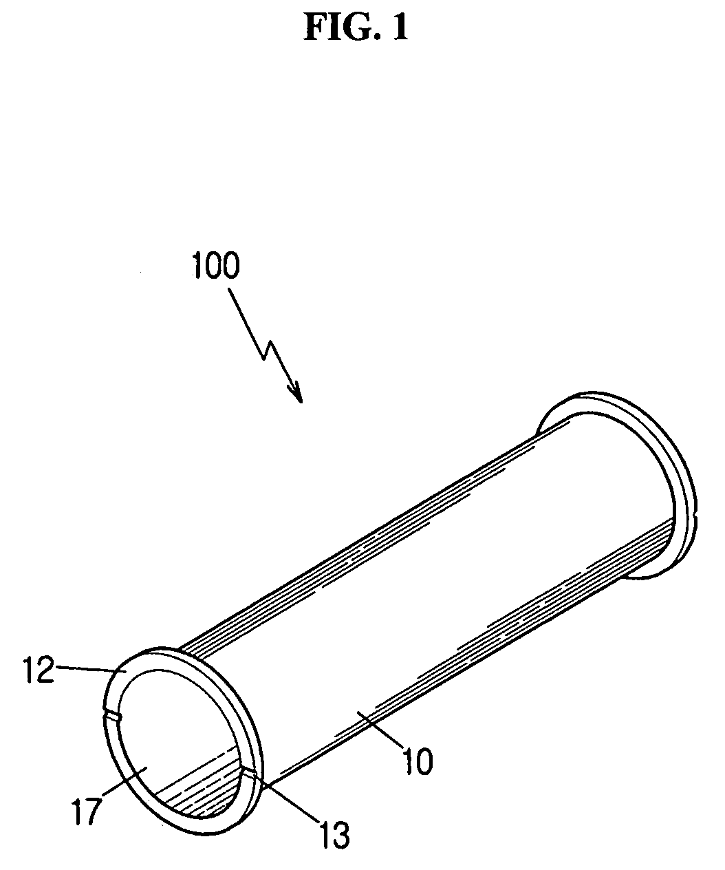
[0032]FIG. 1 is a perspective view of a prefabricated segmental concrete filled tube member 100, which is in a state where the concrete is not filled in a hollow portion 17 of a pipe 10 thereof, according to a preferred embodiment of the present invention, and FIG. 2 is a perspective view illustrating a state where the concrete is filled in the pipe 10.

[0033]As shown in FIGS. 1 and 2, the prefabricated segmental concrete filled tube member 100 of the present invention includes a hollow pipe 10 to be filled with the concrete 11, and a connection flange 12 installed at both ends of the pipe 10. The connection flange 12 is shaped in a ring radially extending from the peripheries of both ends of the pipe 10. When the prefabricated segmental concrete filled tube member 100 is connected with another adjacent prefabricated segmental concrete fill...


PUM

PropertyMeasurementUnit
timeaaaaaaaaaa
altitudeaaaaaaaaaa
rigidityaaaaaaaaaa

Abstract

A method of installing segmental concrete filled tube members. The prefabricated segmental concrete filled tube member has a hollow pipe filled therein with concrete, and a connection flange shaped in a ring radially extending from the peripheries of both ends of the pipe, wherein the segmental concrete filled tube member is integrally connected with another adjacent segmental concrete filled tube member by the connection flange.

Description

CROSS-REFERENCE TO RELATED APPLICATIONS[0001]This application claims all benefits of Korean Patent Applications No. 2005-74639 filed on Aug. 16, 2005 and No. 2005-121674 filed on Dec. 12, 2005 in the Korean Intellectual Property Office, the disclosures of which are incorporated herein by reference.BACKGROUND OF THE INVENTION[0002]1. Field of the invention[0003]The present invention relates to a prefabricated segmental concrete filled tube member, and fabrication structure and method using the same, and more particularly, to a prefabricated segmental concrete filled tube member capable of being easily assembled in short time for use in a bridge pier or a main girder, and so on, and fabrication structure and method using the same.[0004]2. Description of the Prior Art[0005]Members used in a bridge pier or a main girder and so on have been generally constructed with concrete structures. However, since such concrete structures are constructed at in situ site, there are drawbacks in that ...

Claims


Application Information

Patent Timeline
Patent Type & Authority Patents(United States)
IPC IPC(8): E01D21/00E01D22/00
CPCE01D2/00E01D19/02E01D21/00E04C3/22E04C3/26E04C3/34E04C3/44E01D2101/268E01D2101/285E01D2101/40
Inventor KIM, SEONG-WOONKIM, YOUNG-JINKIM, IN-GYUJIN, BYEONG-MOOKIM, TAE-HOONMA, HYANG-WOOKLEE, YUN-SEOK
Owner DAEWOO ENG & CONSTR CO LTD
Why Eureka
Eureka Blog
Learn More