
All-solid-state reflection-controllable electrochromic device and optical switchable component using it

a technology of electrochromic devices and optical switchable components, applied in non-linear optics, instruments, optics, etc., can solve the problems of increasing the cost, reducing the comfort level of the vehicle, and riding in an automobile under such conditions. achieve the effect of rapid diffusion speed

Inactive Publication Date: 2009-06-09
NAT INST OF ADVANCED IND SCI & TECH +1
View PDF15 Cites 47 Cited by
  • Summary
  • Abstract
  • Description
  • Claims
  • Application Information

AI Technical Summary

Benefits of technology

The device achieves high transmittance when transparent and enables rapid switching over large areas, effectively controlling radiant energy and maintaining a comfortable interior space by electrically changing the glass surface from a mirrored to a transparent state, addressing the limitations of previous technologies.

Problems solved by technology

In examples of measuring automobile interior temperatures in a summer environment in Japan, the air temperature inside a parked automobile has been found to reach nearly 70° C. In addition, with respect to the temperatures of interior parts and materials inside an automobile, the top of the instrument panel may reach nearly 100° C., while the roof may reach nearly 70° C. It goes without saying that riding in an automobile under such conditions is extremely uncomfortable.
In addition, since the temperature of interior parts and materials does not readily lower even if the interior is ventilated or the air-conditioner is used, passengers continue to be radiated with radiant heat for a long period of time, thereby significantly decreasing the level of comfort within the vehicle.
Since buildings and automobiles are premised on long-term use, although it is possible to prevent leakage of liquid for a long period of time, this leads to higher costs.
However, in the case of employing a light-controllable material having this type of light-control principle, there is the problem of the light-controllable material retaining heat as a result of absorbing light, that heat being re-radiated into the interior, and that heat ending up penetrating into a light-controllable glass.
In this device, however, since expensive rare earth metal is used for the reflection-controllable layer, applications to large surface areas are difficult from the viewpoint of cost.
However, this type of material was unable to be used practically due to the low transmittance when the device is transparent.
However, although the switching time of this device has a short when it changes from a reflecting state to a transparent state in the vicinity of an electrode, it has the problem of that the switching time becomes considerably longer as the distance increases from the electrode, thereby preventing its use in windows and so forth.

Method used


Image

  • All-solid-state reflection-controllable electrochromic device and optical switchable component using it
  • All-solid-state reflection-controllable electrochromic device and optical switchable component using it
  • All-solid-state reflection-controllable electrochromic device and optical switchable component using it

Examples


example 1

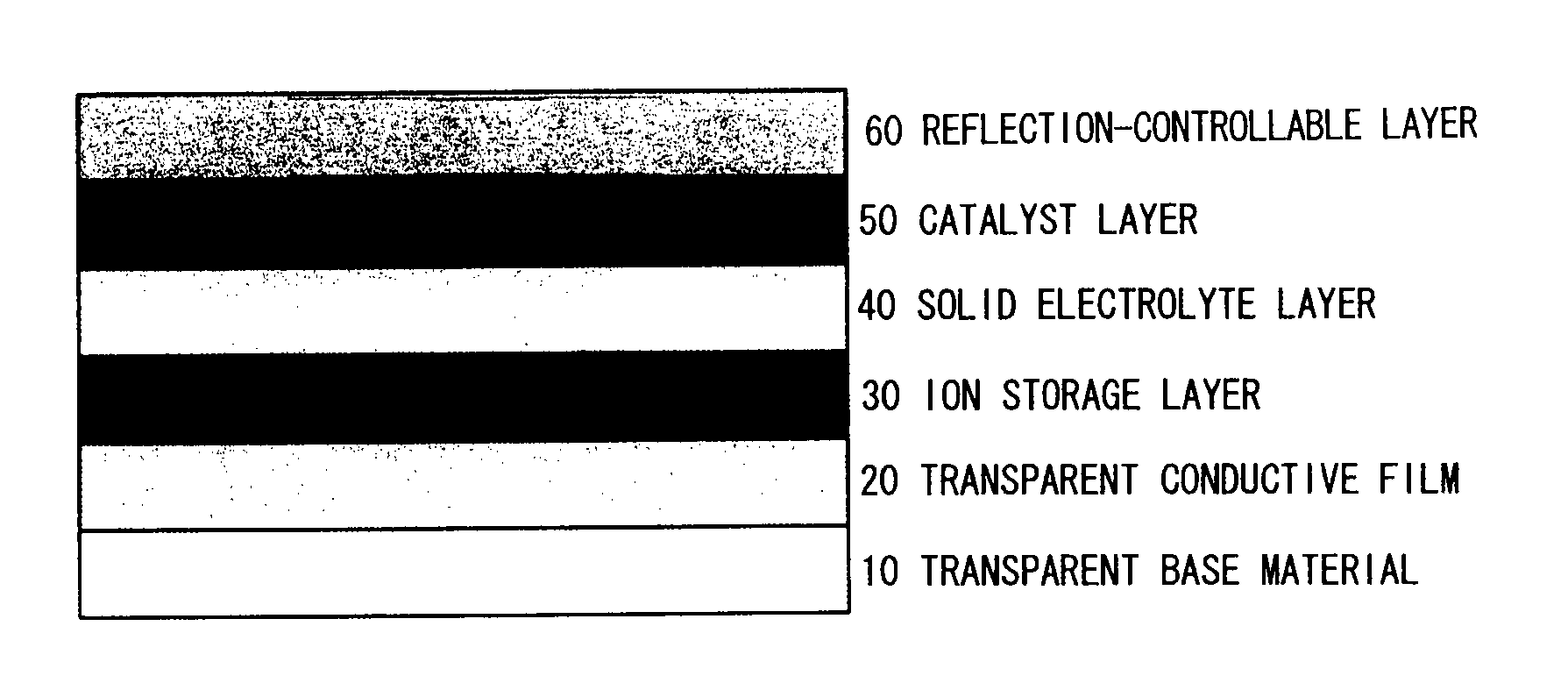
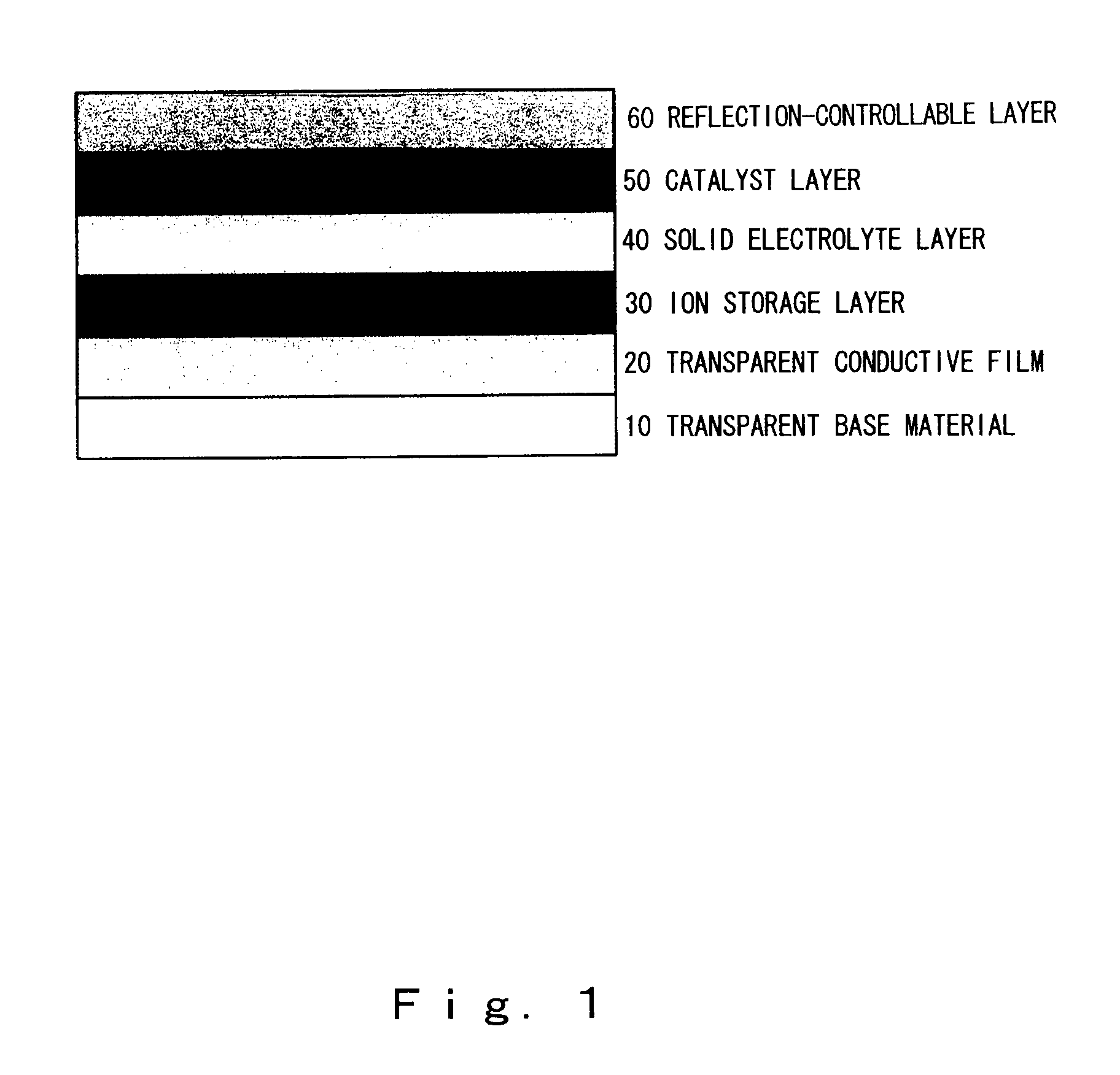
[0077]First, an explanation of a first layer structure of the present invention is provided with reference to FIG. 1. In the present example, the all-solid-state reflection-controllable electrochromic device shown in FIG. 1 was used. Although the following provides an explanation of a process procedure with respect to an embodiment of a production process, the technical scope of the present invention is not limited to the following procedure. An electrochromic device can be produced by, for example, forming a transparent conductive film, a reflection-controllable layer and a catalyst layer on a first base material, followed by forming a transparent conductive film, an ion storage layer and a solid electrolyte layer on a second base material, and then laminating the base materials.

[0078]A glass plate having a surface resistance of 10Ω / □ and thickness of 1 mm and coated with a transparent conductive film in the form of tin-doped indium oxide was used as a substrate. After rinsing, the...

example 2

[0084]The resulting multilayer film was mounted in an evaluation system as shown in FIG. 6 to investigate the optical switching characteristics thereof. A voltage of ±5 V was applied between the tin-doped indium oxide and the indium, and the change in optical transmissivity was measured with a measurement system combining a semiconductor laser having a wavelength of 670 nm and a silicon photodiode.

[0085]Since the reflection-controllable layer has a shiny metallic surface, the as-deposited multilayer film reflects light well (optical reflectance: up to 28%), and since the ion storage layer in the form of a tungsten oxide thin film has a deep blue color, the transmissivity is extremely low (optical transmittance: up to 0.1%). When a −5 V voltage was applied to the indium electrode side of this multilayer film, the protons in the tungsten oxide thin film are released due to electric field effects, are transferred through the solid electrolyte layer, and then are introduced into the mag...


PUM

PropertyMeasurementUnit
densityaaaaaaaaaa
temperaturesaaaaaaaaaa

Abstract

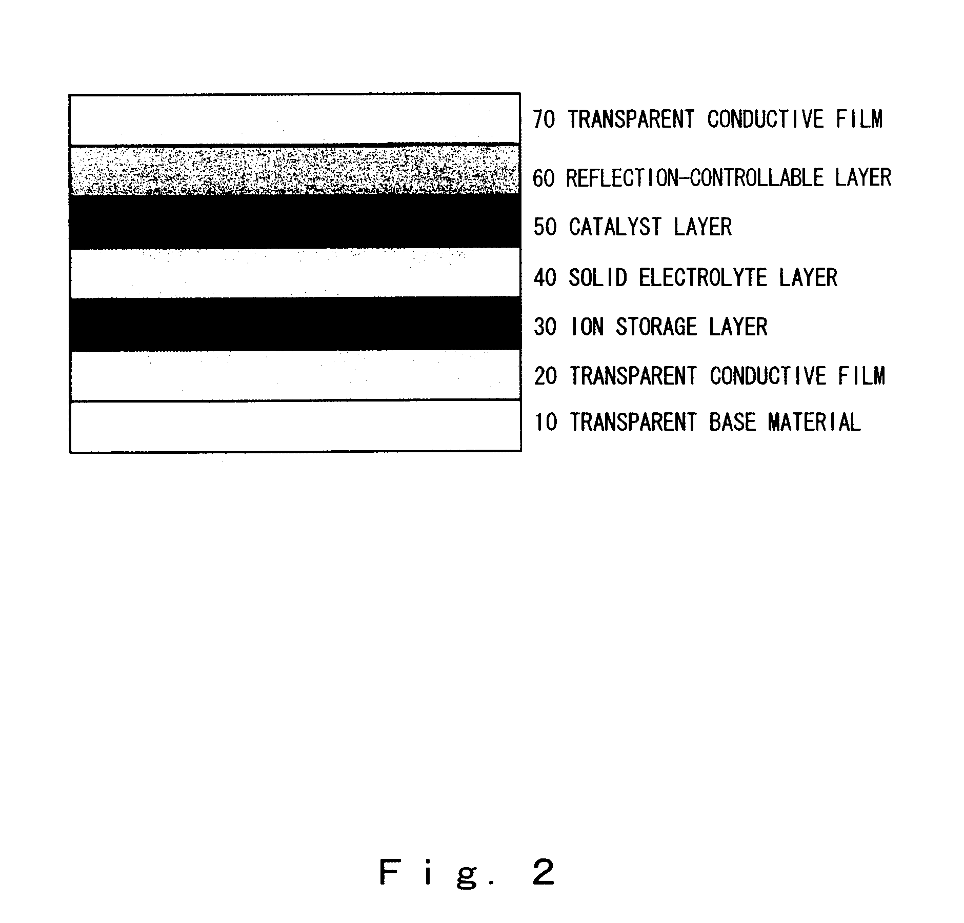
The present invention provides an all-solid-state reflection-controllable electrochromic device and a reflection-controllable member using that device, and the present invention relates to the all-solid-state reflection-controllable electrochromic device, which is a reflection-controllable device in which a multilayer thin film is formed on a transparent base material, wherein, at least a transparent conductive film layer, an ion storage layer, a solid electrolyte layer, a catalyst layer and a reflection-controllable layer using a magnesium-nickel based alloy thin film are formed on the base material; and, a reflection-controllable member incorporating this reflection-controllable electrochromic device, and it is possible to provide a reflection-controllable electrochromic device, having a novel multilayer structure with high transmissivity when transparent and capable of switching in a short period of time over a large surface area, and a reflection-controllable member incorporating this device.

Description

BACKGROUND OF THE INVENTION[0001]1. Field of the Invention[0002]The present invention relates to an all-solid-state reflection-controllable electrochromic device using a magnesium-nickel based alloy thin film, and more particularly, to a novel all-solid-state reflection-controllable electrochromic device capable of electrically controlling the transmission of sunlight entering through window glass by reversibly and electrically changing the glass surface from a mirror state to a transparent state, a production process thereof, and a reflection-controllable member.[0003]The present invention relates to an electrochromic device which has high transmittance when transparent and is capable of switching the state of the glass surface in a short period of time over a large surface area by employing a specific multilayer structure which uses a magnesium-nickel alloy thin film for a reflection-controllable layer. The present invention provides a novel all-solid-state reflection-controllable...

Claims


Application Information

Patent Timeline
Patent Type & Authority Patents(United States)
IPC IPC(8): G02F1/153G02F1/15G02F1/1524
CPCG02F1/1525G02F1/19G02F2001/1536G02F2202/34G02F2203/02G02F1/1524
Inventor YOSHIMURA, KAZUKITAJIMA, KAZUKIYAMADA, YASUSEIOGAWA, HIROSUMIKUMAZAWA, KINYAOKADA, JUN
Owner NAT INST OF ADVANCED IND SCI & TECH
Learn More