
Hybrid antenna using parasitic excitation of conducting antennas by dielectric antennas

a dielectric antenna and conducting antenna technology, applied in the direction of antenna earthing, resonant antenna, radiating element structure, etc., can solve the problem of not being designed to radiate, and achieve the effect of improving bandwidth and increasing bandwidth for cylindrical dielectric resonator antennas

Inactive Publication Date: 2009-06-09
MICROSOFT TECH LICENSING LLC
View PDF15 Cites 26 Cited by
  • Summary
  • Abstract
  • Description
  • Claims
  • Application Information

AI Technical Summary

Benefits of technology

[0021]WO 03/019718 (CNRS et al.) discloses a stripline-fed DRA mounted on a groundplane, with a “parasitic element”50 located on top of the pellet so as to create an asymmetry. The parasitic element 50 is not in itself configured or designed to radiate in a useful manner.
[0022]Electronic Letters, Vol 37, No 7, March 2001, pp 406-408, R. T. Long et al., “Use of a parasitic strip to produce circular polarisation and increased bandwidth for cylindrical dielectric resonator antennas” discloses an arrangement in which one or more parasitic strips are provided on side surfaces of a cylindrical DRA so as to improve bandwidth and to produce ...

Problems solved by technology

Again, the parasitic strips are configured solely to modify resonant characteristics of the DRA, and are not designed to radiate themselves in a useful manner.

Method used


Image

  • Hybrid antenna using parasitic excitation of conducting antennas by dielectric antennas
  • Hybrid antenna using parasitic excitation of conducting antennas by dielectric antennas
  • Hybrid antenna using parasitic excitation of conducting antennas by dielectric antennas

Examples


Embodiment Construction

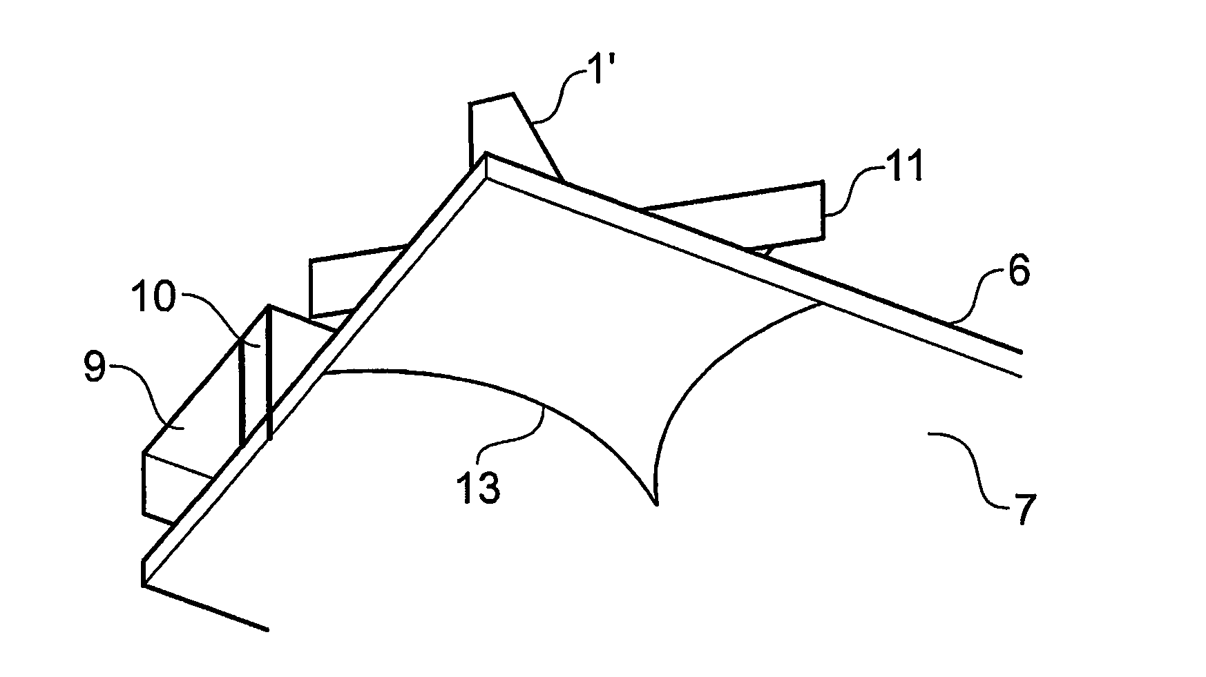
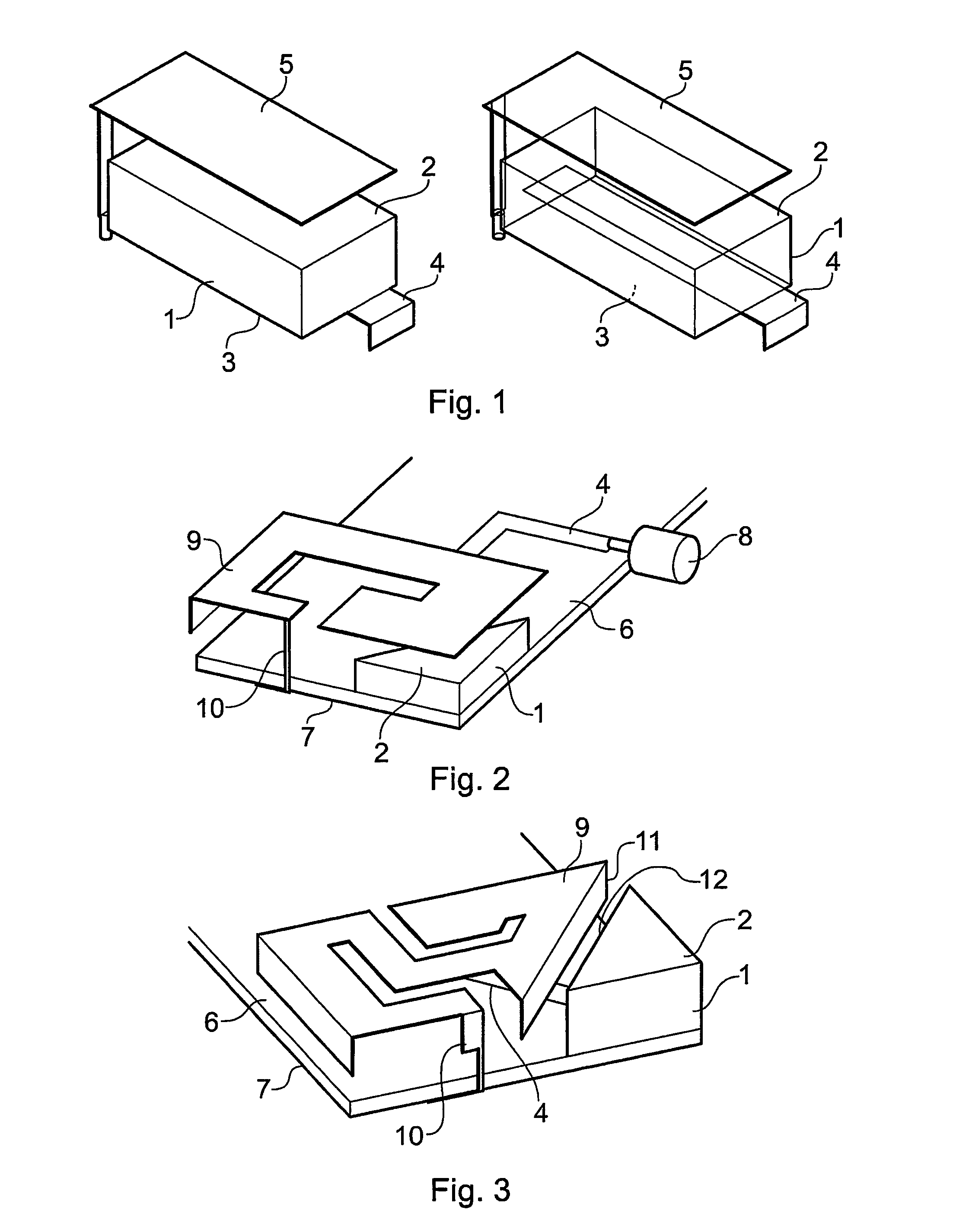
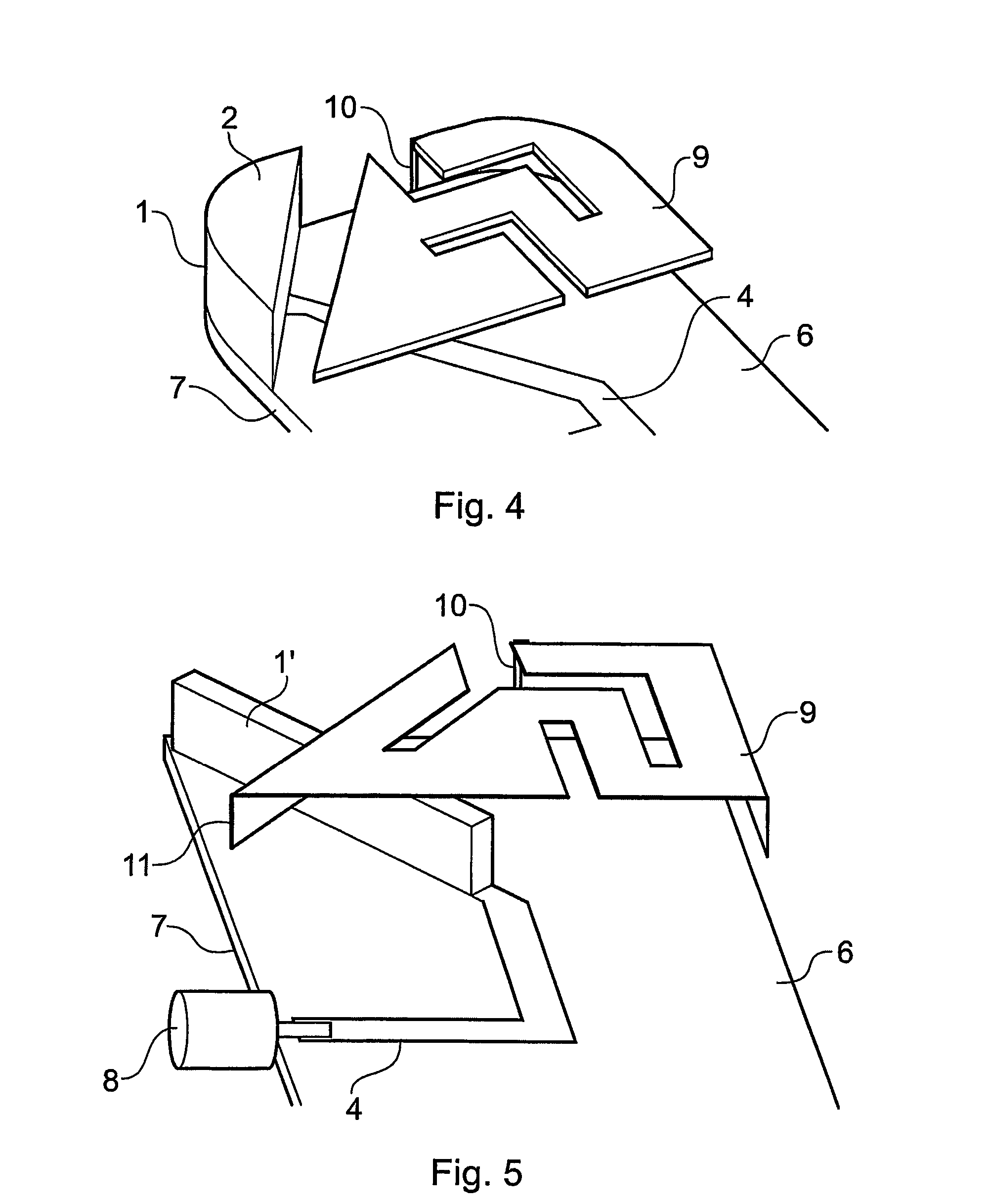
[0034]For the avoidance of doubt, the expression “electrically-conductive antenna components” defines a traditional antenna component such as a patch antenna, slot antenna, monopole antenna, dipole antenna, planar inverted-L antenna (PILA) or any other antenna component that is not a DRA, HDA or DLA. Furthermore, these antenna components are specifically designed to radiate at a predetermined frequency or frequencies in a manner useful for telecommunications applications. The expression “antenna components” does not include parasitic patches or the like that simply modify the resonance characteristics of the dielectric antenna, but only actual antenna components that are configured to radiate in a useful and predetermined manner.

[0035]Additionally, for the purposes of the present application, the expression “dielectric antenna” is hereby defined as encompassing DRAs, HDAs and DLAs, although in some embodiments DRAs are specifically excluded.

[0036]Embodiments of the present invention...


PUM


Abstract

An integrated antenna device comprising a first, dielectric antenna component (1) and a second, electrically-conductive antenna component (9), wherein the first and second components are not electrically connected to each other but are mutually arranged such that the second component is parasitically driven by the first component when the first component is fed with a predetermined signal.

Description

CROSS-REFERENCE TO RELATED APPLICATIONS[0001]This application is a National Phase Application of PCT International Application No. PCT / GB2004 / 002497, International Filing Date Jun. 16, 2004, claiming priority of Great Britain Patent Application 0313890.6, filed Jun. 16, 2003, which are both incorporated by reference herein in their entirety.FIELD OF THE INVENTION[0002]The present invention relates to multi-band antenna structures and techniques for the construction thereof, by using dielectric antennas to excite other non-dielectric electrical parasitic structures. The dielectric antennas include, but are not limited to, dielectric resonator antennas (DRAs), high dielectric antennas (HDAs) and dielectrically loaded antennas (DLAs).BACKGROUND OF THE INVENTION[0003]Dielectric resonator antennas are resonant antenna devices that radiate or receive radio waves at a chosen frequency of transmission and reception, as used in for example in mobile telecommunications. In general, a DRA cons...

Claims


Application Information

Patent Timeline
IPC IPC(8): H01Q1/38H01Q1/24H01Q5/10H01Q5/378H01Q9/04
CPCH01Q5/378H01Q9/0485H01Q1/24H01Q5/00H01Q9/04
Inventor IELLICI, DEVISKINGSLEY, SIMON PHILIPKINGSLEY, JAMES WILLIAMO'KEEFE, STEVEN GREGORYTYLER, SCOTT WILLIAM SPENCER
Owner MICROSOFT TECH LICENSING LLC
Learn More