
Device and method for power amplifier noise reduction

a power amplifier and noise reduction technology, applied in the field of power amplifiers, can solve the problems of ballast resistors generating amplified noise, cost of a higher bias circuit supply voltage, etc., and achieve the effect of reducing the noise in the receiver

Active Publication Date: 2009-06-09
SKYWORKS SOLUTIONS INC
View PDF1 Cites 1 Cited by
  • Summary
  • Abstract
  • Description
  • Claims
  • Application Information

AI Technical Summary

Benefits of technology

[0015]Another embodiment of the present invention is directed to a method of reducing the noise in a receiver of a wireless communication device, the method comprising the steps of: providing a wireless communication device comprising a HBT power amplifier for amplifying a modulated signal characterized by a transmit frequency and a low noise amplifier for amplifying a received signal characterized by a receive frequency, the receive and transmit frequencies differing by a frequency offset; providing a base bias signal to a base terminal of the HBT power amplifier; and removing from the base bias signal a plurality of signal components characterized by a predetermined frequency.

Problems solved by technology

In general, a larger ballast resistor increases thermal runaway protection but at the cost of a higher bias circuit supply voltage.
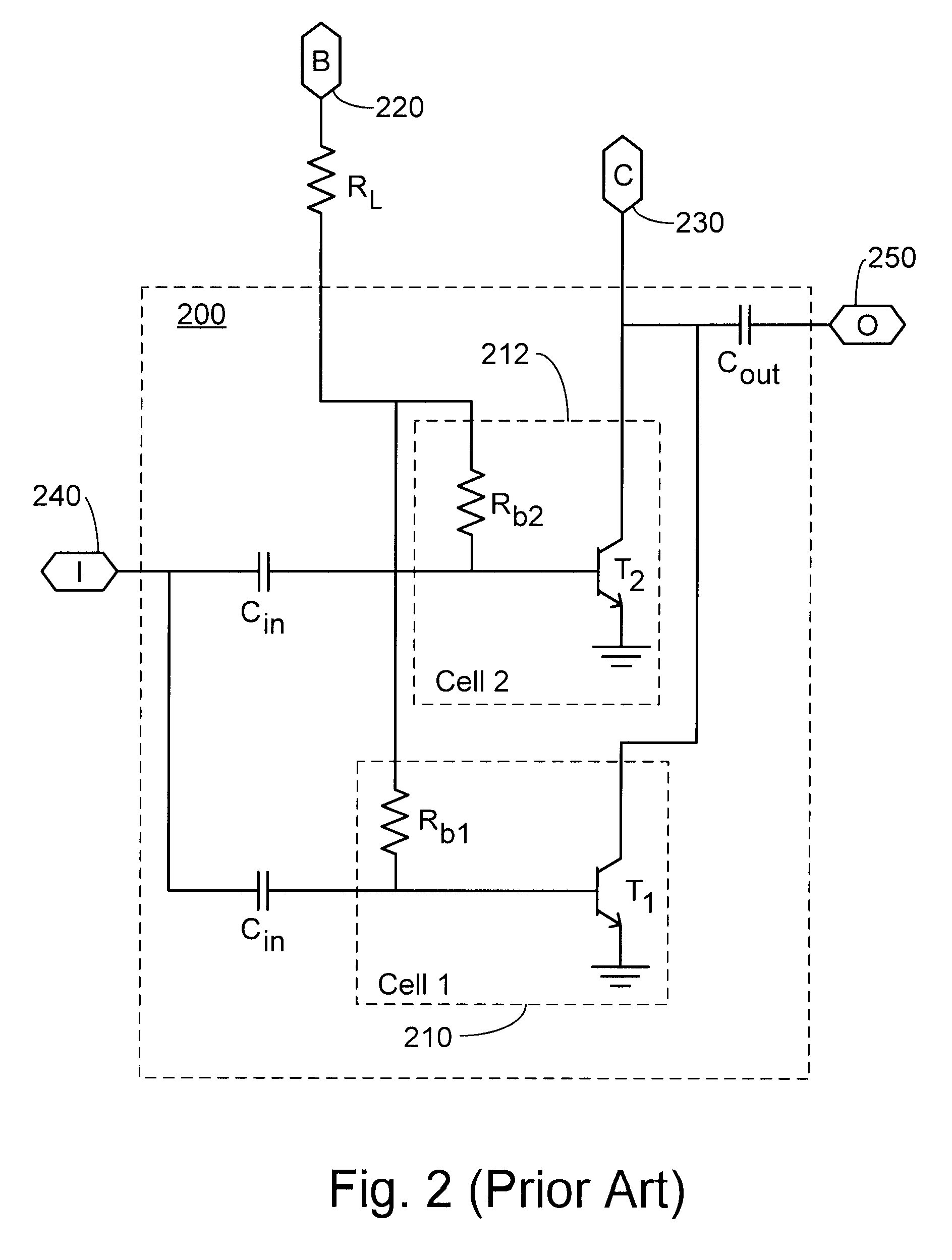
Ballast resistors also generate noise that is amplified with the RF signal input to the HBT.
Regardless of the noise source, the noise at the base of the HBT may mix up or up-convert, such that the amplified signal spills into nearby channels as noise such as, for example, the receive band of the mobile device.

Method used


Image

  • Device and method for power amplifier noise reduction
  • Device and method for power amplifier noise reduction
  • Device and method for power amplifier noise reduction

Examples


Embodiment Construction

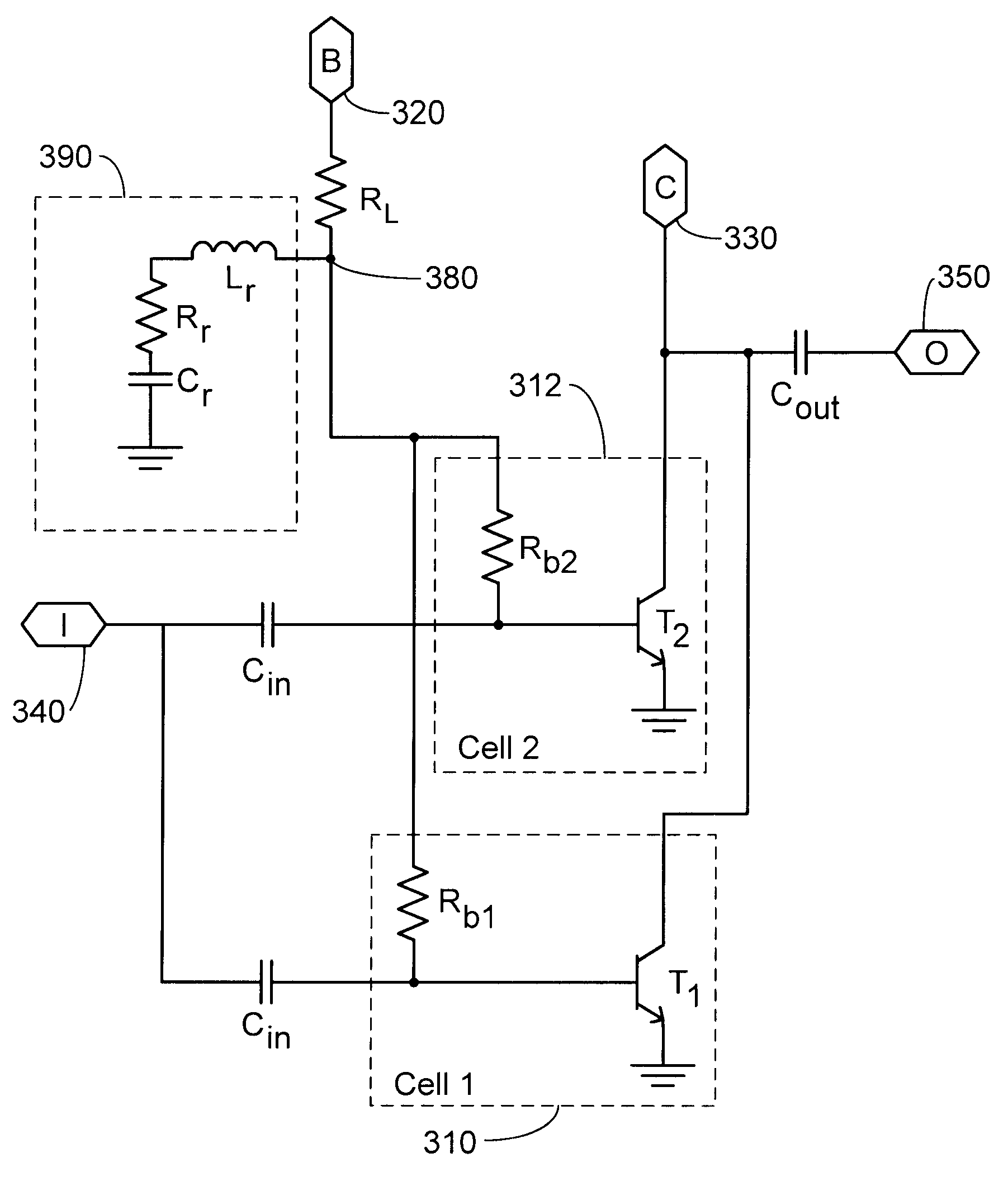
[0023]FIG. 3 is a schematic diagram of an HBT power amplifier in an embodiment of the present invention. A two-cell HBT is shown in FIG. 3 for the purposes of illustration only and it is understood that the present invention is not limited to two-cell HBT amplifiers but encompasses HBT amplifiers comprising at least one cell. In FIG. 3, each cell 310, 312 includes a cell transistor, T1, T2, and a ballast resistor, Rb1, Rb2 connected to the base of the cell transistor. Each ballast resistor prevents thermal runaway for its cell transistor. The ballast resistors are connected in parallel to each other and in series with a lumped resistor, RL, which may be used to modify the impedance of the bias or improve amplifier stability. For a single cell HBT, the ballast resistor and the lumped resistor may be combined into a single resistor. The lumped resistor is connected to a base port 320, which provides a connection to the base biasing network. The collectors of the cell transistors T1, T...


PUM


Abstract

A power amplifier for use in wireless communication devices is disclosed that reduces the noise generated at the output of the amplifier in the receive band of the wireless communication device. A resonant circuit is inserted between the base ballast resister and the lumped resister. The resonant frequency of the resonant circuit is adjusted to correspond to the frequency offset between the transmission frequency and the frequency corresponding to the peak noise in the receive band of the communication device.

Description

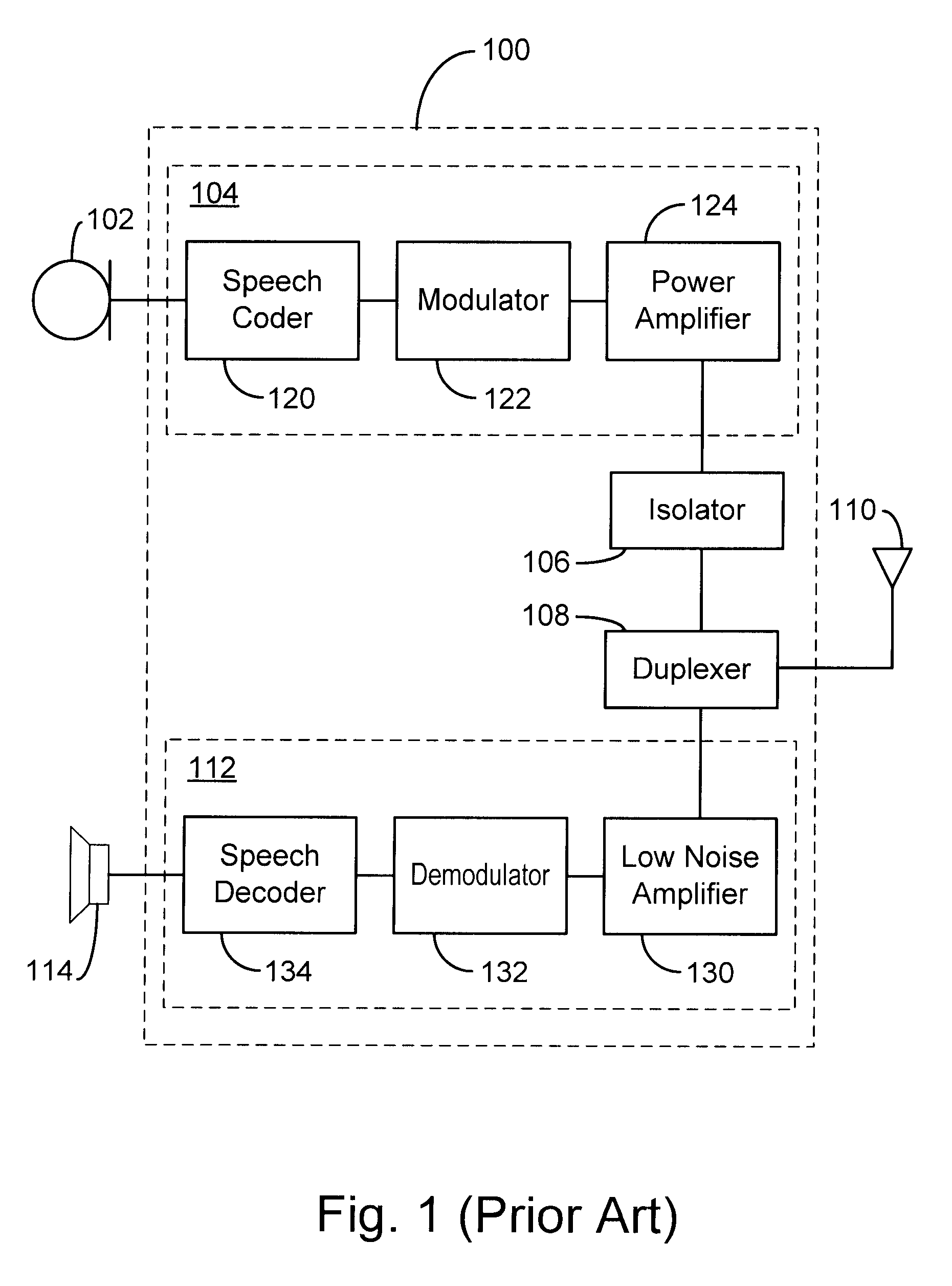
CROSS REFERENCE TO RELATED APPLICATIONS[0001]The present application is a divisional of application Ser. No. 10 / 984,316 filed Nov. 8, 2004, now U.S. Pat. No. 7,348,852.BACKGROUND OF THE INVENTION[0002]1. Field of the Invention[0003]The present invention relates to power amplifiers for mobile communication devices. More specifically, the invention relates to methods and devices for reducing noise in the power amplifier.[0004]2. Description of the Related Art[0005]Wireless communication is ubiquitous in our modern society because of its convenience and ease of use. FIG. 1 shows a diagram of a typical wireless voice communication device 100, such as a mobile phone handset 100 for cellular telephone use. For the voice interface, device 100 includes a microphone 102 for converting audio signals to electrical signals that are transmitted by transmitter 104. Device 100 also includes a receiver 112 connected to a speaker 114. The transmitter 104 and the receiver 112 normally share an antenn...

Claims


Application Information

Patent Timeline
IPC IPC(8): H03F3/04
CPCH03F1/26H03F3/19H03F2200/181H03F2200/372
Inventor OZARD, KENNETH SEAN
Owner SKYWORKS SOLUTIONS INC
Learn More