
Reciprocating pump performance prediction

a technology of reciprocating pump and performance prediction, which is applied in the direction of machines/engines, process and machine control, nuclear elements, etc., can solve the problems of unplanned downtime, affecting the operating performance and operational life of the pump, and costly unscheduled maintenance and repair

Active Publication Date: 2009-06-02
PERFORMANCE PULSATION CONTROL
View PDF7 Cites 17 Cited by
  • Summary
  • Abstract
  • Description
  • Claims
  • Application Information

AI Technical Summary

Benefits of technology

[0008]To address the above-discussed deficiencies of the prior art, it is a primary object of the present invention to provide, for use in hydraulic pulsation systems (such as reciprocating pump systems), monitoring of performance parameters including pulsation energy, temperature energy, solids, Miller number and chemical energy and the like for use in at least periodically computing a total energy number over the operating life of the system. The current computed value is compared to a predictive failure value empirically determined for at least one part of the system. This comparison aids in determining when failure is likely to be imminent. Scheduling of maintenance with other system operations and objective rating of competing designs is possible based on the total energy number.

Problems solved by technology

In addition, periodic service, remote locations and / or hazardous conditions are other factors that can affect the operating performance and operational life of the pump.
Random failure of critical pump parts create many operational problems, including unplanned downtime, costly unscheduled maintenance and repair, emergency callout of maintenance personnel, and loss of operating revenue.
Pumps are not generally monitored due to the insufficient benefits warranting the additional expense.
Even if such monitoring were to take place, it is likely only to alert the operator that a problem has arisen and cannot currently predict an impending failure.
Operating in less than ideal conditions may result in damage to parts of the system and / or degrade performance.
Fluctuations in operation are sometimes extremely short in duration, and may not be captured by conventional recording or acquisition equipment.
Moreover, the equipment operator may not always know exactly what specific anomalies or failures have occurred.
In addition, irregular or inconsistent maintenance could lead to early failure.
Remote locations requiring frequent visits to check operation quality contribute to both the difficulty and the expense of maintaining operation.
Likewise, no method of predicting part life currently exists.

Method used


Image

  • Reciprocating pump performance prediction
  • Reciprocating pump performance prediction
  • Reciprocating pump performance prediction

Examples


Embodiment Construction

[0017]FIGS. 1 through 5, discussed below, and the various embodiments used to describe the principles of the present invention in this patent document are by way of illustration only and should not be construed in any way to limit the scope of the invention. Those skilled in the art will understand that the principles of the present invention may be implemented in any suitably arranged device.

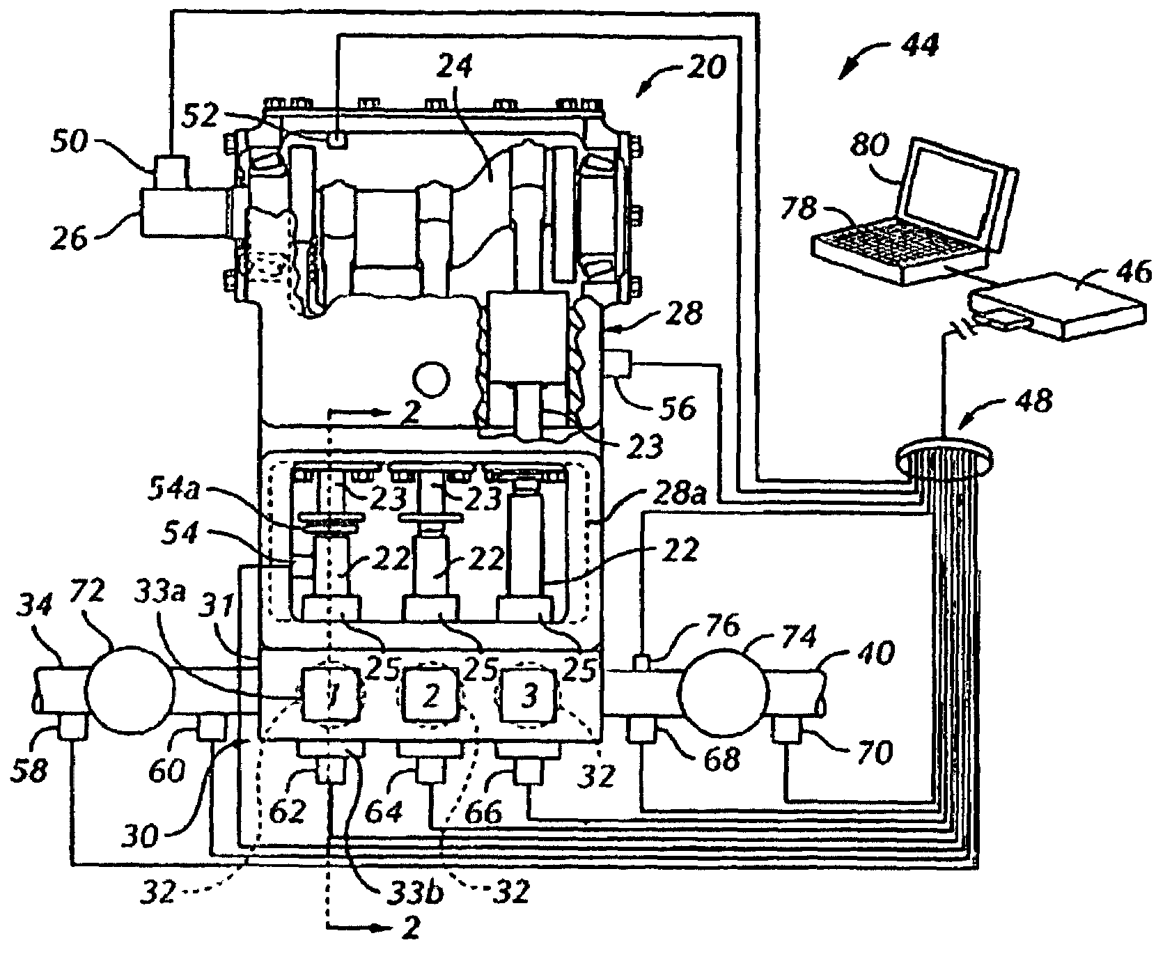
[0018]FIG. 1 depicts a top plan and somewhat schematic view of a reciprocating pump with a performance monitoring and prediction system according to an exemplary embodiment of the present invention, while FIG. 2 is a longitudinal central section view taken generally along line 2-2 of FIG. 1. Pump 20 may be one of a type well-known and commercially available. Preferably, pump 20 is a so-called triplex plunger pump. Pump 20 is configured to reciprocate three spaced apart plungers or pistons 22, each connected by suitable connecting rod and crosshead mechanisms, as shown, to a rotatable crankshaft...


PUM


Abstract

Performance parameters for a reciprocating pump including pulsation energy, temperature energy, solids, Miller number and chemical energy and the like are monitored and employed to at least periodically compute a total energy number over the operating life of the pump. The current computed value is compared to a predictive failure value empirically determined for the respective pump design, to determine when failure is likely to be imminent. Scheduling of maintenance with other pumping operations and objective rating of competing designs is possible based on the total energy number.

Description

CROSSREFERENCE TO RELATED APPLICATION AND CLAIM OF PRIORITY[0001]The present application is related to U.S. Provisional Patent No. 60 / 662,734, filed Mar. 17, 2005, entitled “RECIPROCATING PUMP PERFORMANCE PREDICTION”. U.S. Provisional Patent No. 60 / 662,734 is assigned to the assignee of the present application and is hereby incorporated by reference into the present disclosure as if fully set forth herein. The present application hereby claims priority under 35 U.S.C §119(e) to U.S. Provisional Patent No. 60 / 662,734.TECHNICAL FIELD OF THE INVENTION[0002]The present invention is directed, in general, to the operation of reciprocating systems and, more specifically, to predicting performance of such reciprocating systems to avoid catastrophic failure.BACKGROUND OF THE INVENTION[0003]Reciprocating systems (such as reciprocating pump systems) and similar equipment operate in many types of cyclic hydraulic applications. The operating performance K variables of such equipment include, but...

Claims


Application Information

Patent Timeline
Patent Type & Authority Patents(United States)
IPC IPC(8): F04B49/00G01M99/00
CPCF04B51/00F04B2201/0201
Inventor ROGERS, JOHN THOMAS
Owner PERFORMANCE PULSATION CONTROL
Learn More