
DV/dt-detecting overcurrent protection circuit for power supply

a protection circuit and power supply technology, applied in the direction of electronic switching, emergency protection arrangements for limiting excess voltage/current, pulse techniques, etc., can solve the problem of power loss of approximately 0.9 watt, and achieve the effect of improving overcurrent protection and less power loss

Active Publication Date: 2009-06-02
LUTRON TECH CO LLC
View PDF15 Cites 3 Cited by
  • Summary
  • Abstract
  • Description
  • Claims
  • Application Information

AI Technical Summary

Benefits of technology

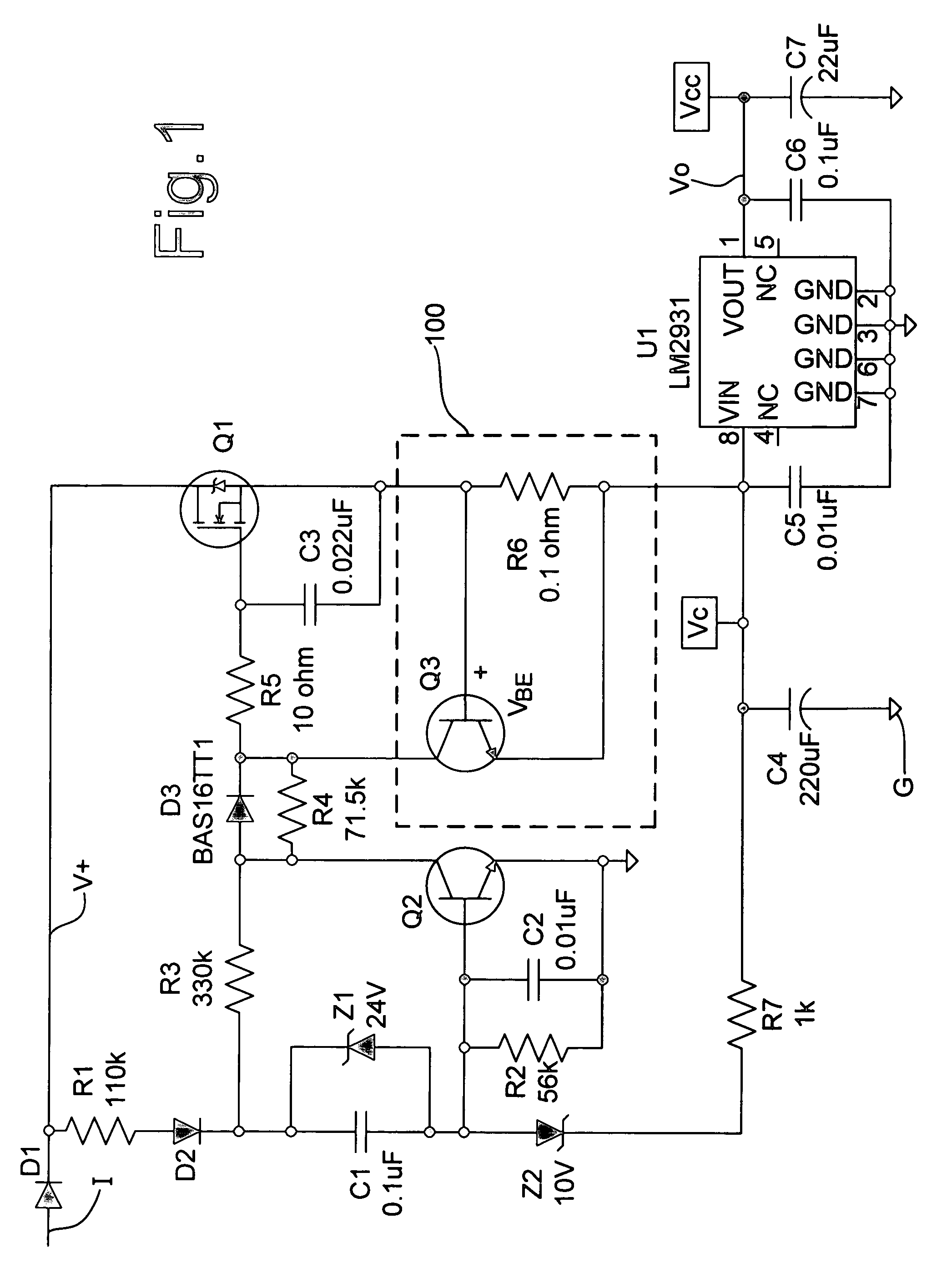
"The present invention provides an improved overcurrent protection circuit for a power switching transistor that results in less power loss than the circuit described above. The circuit includes a protection switch that senses the rate of change of voltage at one of the main electrodes of the power switching transistor and controls the protection switch to remove the control signal to the control electrode of the power switching transistor if the rate of change exceeds a predefined value. This helps to quickly turn off the power switching transistor to prevent damage to the circuit."

Problems solved by technology

The resistor R6 passes the full load current and accordingly, results in a power loss on the order of approximately 0.9 watt for current levels of approximately 3 amps.

Method used


Image

  • DV/dt-detecting overcurrent protection circuit for power supply
  • DV/dt-detecting overcurrent protection circuit for power supply
  • DV/dt-detecting overcurrent protection circuit for power supply

Examples


Embodiment Construction

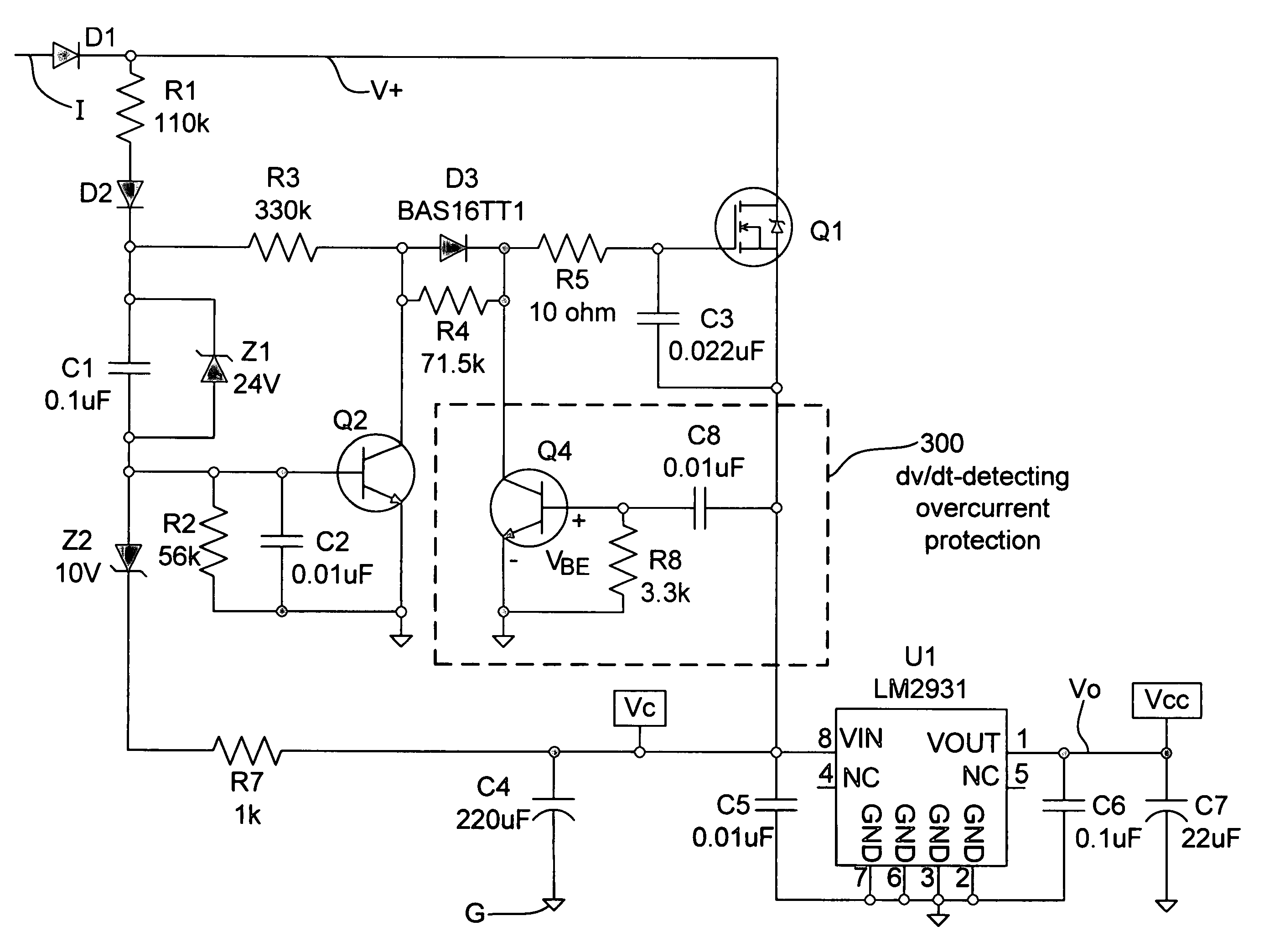
[0018]With reference now to FIG. 3, a new overcurrent protection circuit 300 is provided according to the invention. The overcurrent protection circuit includes a transistor Q4, a capacitor C8 and a resistor R8. This circuit operates as follows. During normal operation, the voltage VBE between the base and emitter of transistor Q4 is less than about 0.3 volts corresponding to a maximum normal operating dV / dt at the source of transistor Q1, determined by the rise time of the ripple voltage on capacitor C4. This is insufficient to turn transistor Q4 on. The circuit is designed such that at approximately twice the normally developed dV / dt, the VBE of transistor Q4 is approximately 0.6 volts. This will be adequate to turn transistor Q4 on, thereby removing the gate drive from transistor Q1 and turning the power transistor Q1 off. Accordingly, when the dV / dt exceeds a predefined value, corresponding to an overcurrent, the base drive to transistor Q4 is adequate to turn it on.

[0019]If the...


PUM


Abstract

An overcurrent protection circuit for a power switching transistor wherein the power switching transistor has a control electrode and two main electrodes, the circuit comprising a circuit including a protection switch for sensing the rate of change of voltage with respect to time at one of the main electrodes of the power switching transistor and for controlling the protection switch to remove a control signal to the control electrode of the power switching transistor to turn off the power switching transistor if the rate of change exceeds a predefined value.

Description

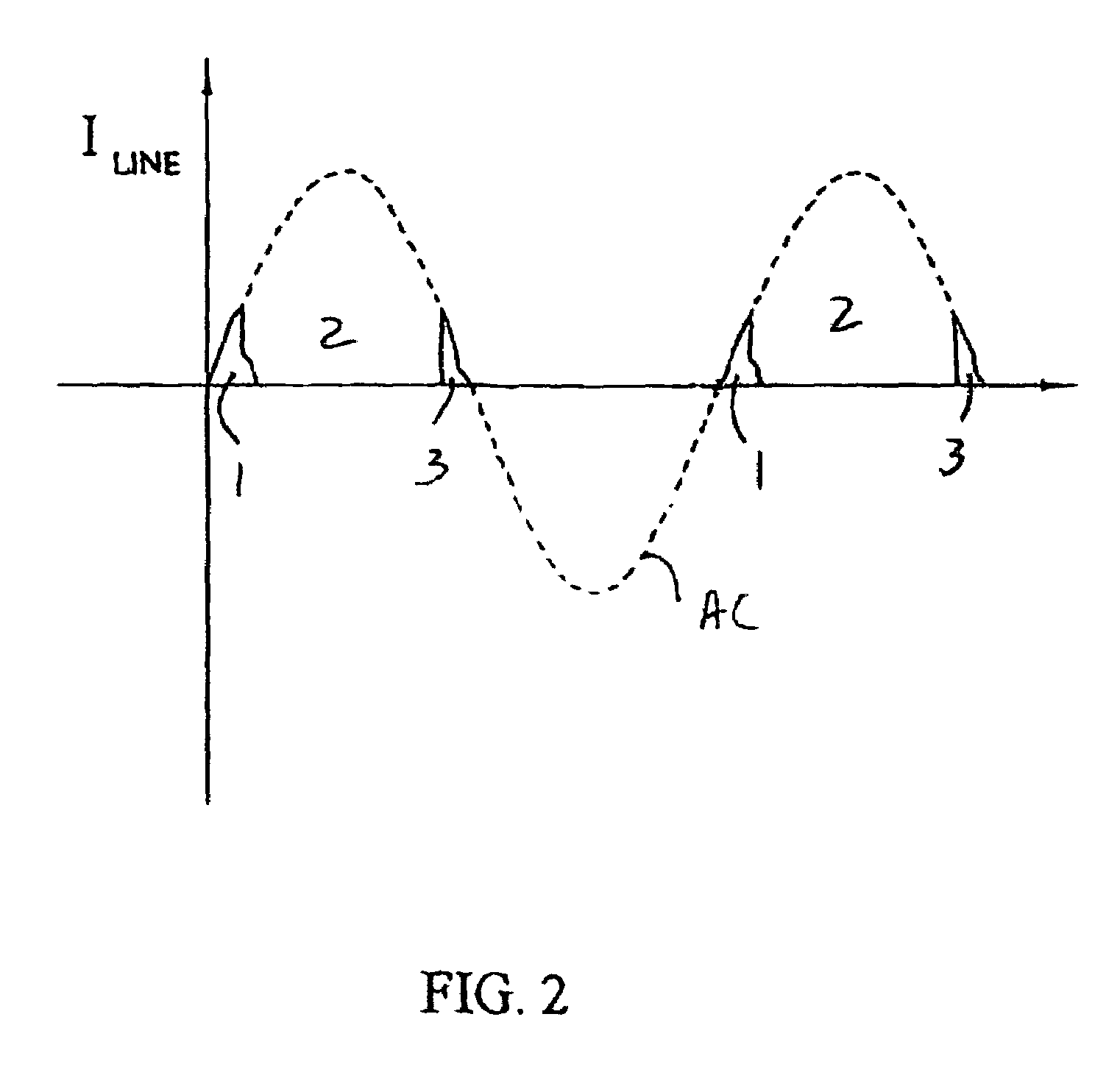
CROSS REFERENCE TO RELATED APPLICATION[0001]The present application is related to U.S. application Ser. No. 10 / 458,608 filed Jun. 10, 2003 and entitled “HIGH EFFICENCY OFF-LINE LINEAR POWER SUPPLY”, the entire disclosure of which is incorporated by reference herein.BACKGROUND OF THE INVENTION[0002]The present invention relates to an overcurrent protection circuit for electrical systems, such as power supplies, and in particular, an off-line high efficiency linear power supply.[0003]In the above-identified U.S. patent application Ser. No. 10 / 458,608, a high efficiency off-line linear power supply is described. The power supply is designed to provide current to electronic circuits during a time period when a dimmer circuit for electric lamps is not drawing current. In particular, the power supply is designed to draw current for powering electronic circuits during time periods when the triac of the dimmer circuit is off.[0004]With reference to FIG. 2, this figure shows an AC waveform (...

Claims


Application Information

Patent Timeline
Patent Type & Authority Patents(United States)
IPC IPC(8): H02H3/08H02H9/02H03K17/08H02M7/217H03K17/082
CPCH02M7/2176H03K17/0822
Inventor BLACK, RICHARD L.
Owner LUTRON TECH CO LLC
Learn More