Data processing method and ink jet printing apparatus
a data processing method and ink jet technology, applied in the direction of printing, other printing apparatus, etc., can solve the problems of ink ejection volume becoming too small, ejection failure becoming more likely to occur, ejection failure, etc., to reduce the change in image density
- Summary
- Abstract
- Description
- Claims
- Application Information
AI Technical Summary
Benefits of technology
Problems solved by technology
Method used
Image
Examples
embodiment 1
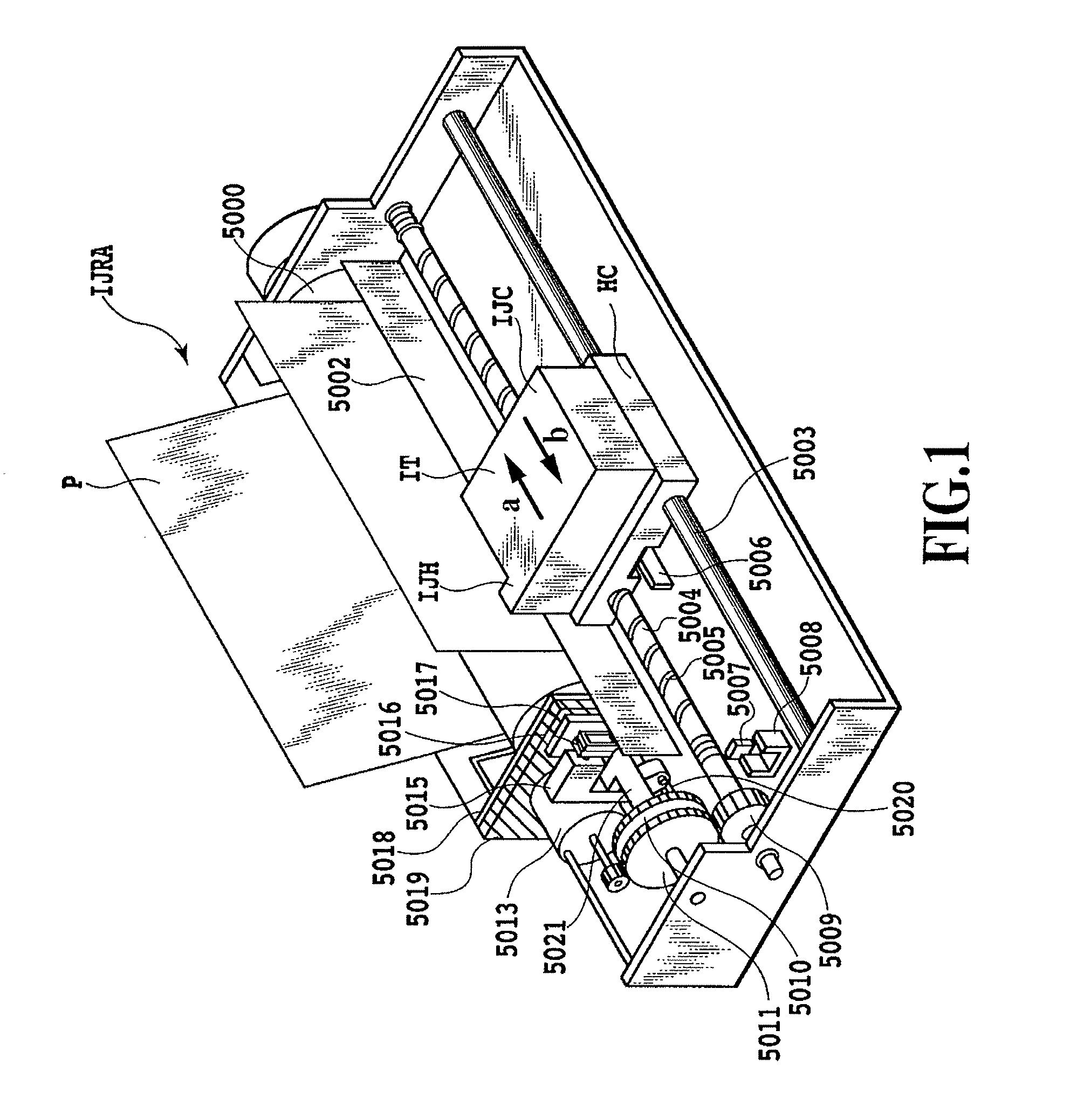
[0028]FIG. 1 is a perspective view showing an ink jet printer IJRA as one embodiment of the ink jet printing apparatus according to this invention. In the figure, a carriage HC mounts an ink tank IT accommodating ink and an integrated ink jet cartridge IJC incorporating a print head that ejects ink toward a print medium P such as print paper.
[0029]The print paper P is held between a paper retainer 5002 arranged opposite the ink jet cartridge IJC and a rotatably mounted platen 5000. The carriage HC engages a spiral groove 5004 of a lead screw 5005 so that a rotating force of a drive motor 5013 is transmitted to the carriage HC through drive force transmission gears 5009-5011. The carriage HC has a pin (not shown) and reciprocally moves, supported on a guide rail 5003, in directions of arrow a and b.
[0030]At one end in its moving direction, the carriage HC has a lever 5006, which is detected by two photocouplers 5007, 5008 installed in the printing apparatus to determine a home positi...
embodiment 2
[0077]In embodiment 1 ejection data is generated by storing preliminary ejection data in a ROM beforehand, comparing the binary preliminary ejection data with image data and preliminary ejection data read of ROM. However, the ejection data is generated by not having preliminary ejection data beforehand but referencing image data as the preliminary ejection data is added in this embodiment. In addition, as in embodiment 1, if the image data exists in the vicinity pixel for which the image data exist, it performs the data processing for not ejecting ink at the vicinity pixel, an ink ejection is not performed to the vicinity pixel, in this embodiment 2.
[0078]FIG. 8 is a block diagram showing a control configuration for image processing in the second embodiment. This control configuration is similar to that of embodiment 1 shown in FIG. 2 except that the control configuration of embodiment 2 does not have the ROMβ that stores on-paper preliminary ejection data beforehand.
[0079]Now, the ...
embodiment 3
[0096]In embodiment 1 and embodiment 2, the print buffer 229 has a memory capacity of one scan. The print buffer 229 may have less than the capacity of one scan, for example one-half the capacity of one scan.
[0097]FIG. 11 is a block diagram showing details of the print buffer of this embodiment. As shown in the figure, the capacity 202 of the print buffer is divided into five blocks 203 to 207. When a predetermined volume of data is accumulated in the internal capacity of the print buffer, the MPU 221 starts the print medium feeding operation by the transport drive system 224 through the ASIC 222. Each time the data is read out, the next block of data is saved, using the memory in a toggle-like fashion. The image controller has a memory capacity of less than one scan, so the data of one scan is divided and the divided blocks of data are sequentially processed.
[0098]Since at the start of one scan this embodiment cannot reference image data up to the end of one scan, only a limited nu...
PUM
 Abstract
Description
Claims
Application Information
 - R&D
- Intellectual Property
- Life Sciences
- Materials
- Tech Scout
- Unparalleled Data Quality
- Higher Quality Content
- 60% Fewer Hallucinations
Browse by: Latest US Patents, China's latest patents, Technical Efficacy Thesaurus, Application Domain, Technology Topic, Popular Technical Reports.
© 2025 PatSnap. All rights reserved.Legal|Privacy policy|Modern Slavery Act Transparency Statement|Sitemap|About US| Contact US: help@patsnap.com


