
Low-profile cable

Inactive Publication Date: 2009-05-19
COMMSCOPE TECH LLC
View PDF10 Cites 2 Cited by
  • Summary
  • Abstract
  • Description
  • Claims
  • Application Information

AI Technical Summary

Benefits of technology

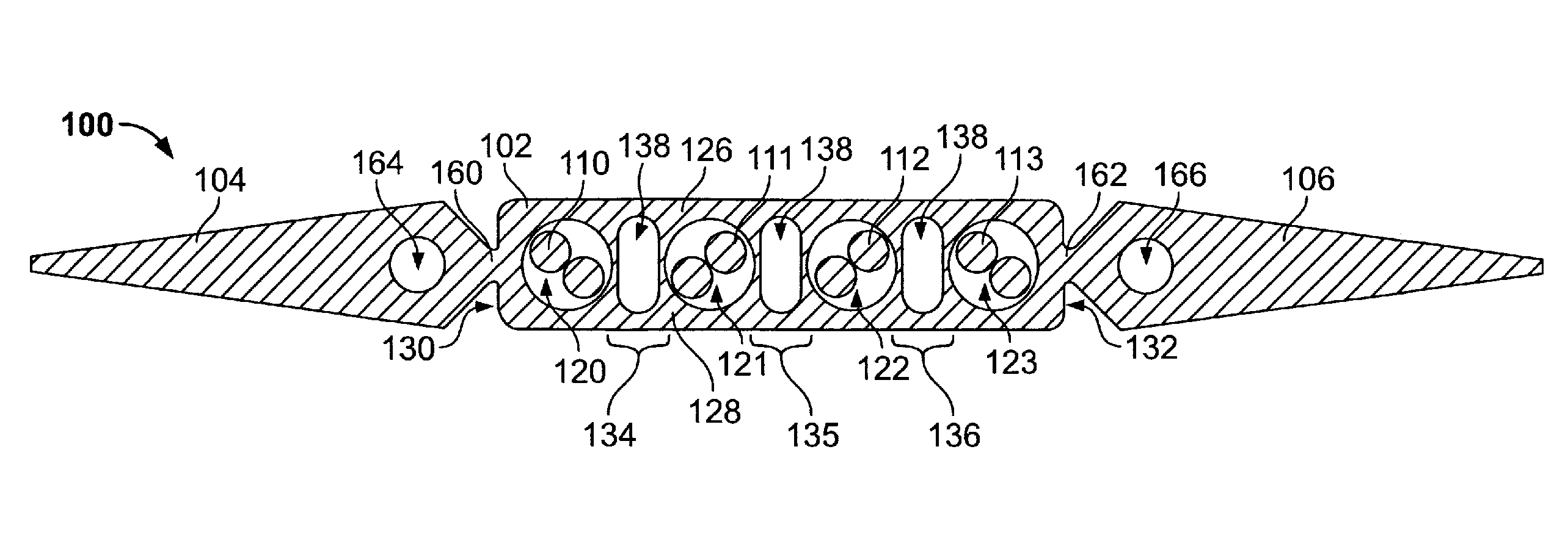
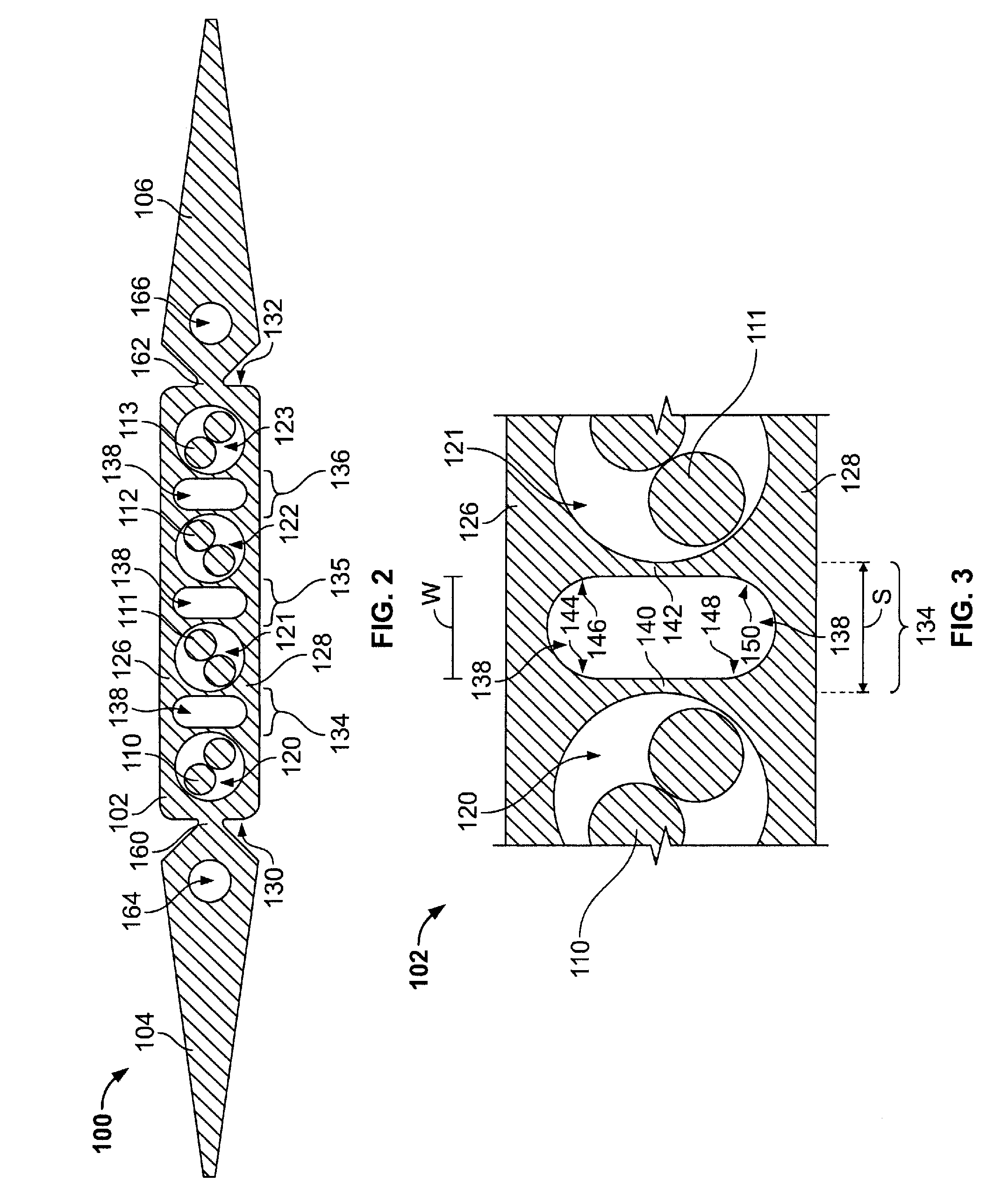
[0007]In one embodiment, a low-profile cable is provided and includes a body having upper and lower portions that extend a length of the body and also having opposite sidewalls joining the upper and lower portions to one another. The cable also includes passages that are located between the sidewalls. The passages extend the length of the body and are configured to receive at least one twisted pair of conductors. Also, the cable includes a load-bearing structural section that spans between the upper and lower portions. The structural section includes opposing wall supports separated by a pocket channel therebetween. The structural section is configured to support the upper and lower portions and substantially resist deformation of the passages when external forces are induced onto at least one of the upper and lower portions.
[0009]In another embodiment, a low-profile cable is provided and includes a body having upper and lower portions that extend a length of the body and also having opposite sidewalls that join the upper and lower portions to one another. The cable also includes passages located between the sidewalls. The passages extend the length of the body. The cable further includes a load-bearing structural section that spans between the upper and lower portions. The passages are configured to receive only a single twisted pair of conductors. The structural section is configured to support the upper and lower portions and substantially resist deformation of the passages when external forces are induced onto at least one of the upper and lower portions.

Problems solved by technology

While underneath the carpet or flooring, the cable may be subjected to external forces, such as from people walking over the cable and / or equipment rolling or resting over the cable.
These compressive forces may move and / or damage the electrical conductors within the corresponding passages.
Furthermore, if the electrical conductors form twisted pairs, the twisted relationship of the conductors may be altered or disrupted thereby affecting the performance of the cable.
However, if the external forces are focused onto an area over one of the rectangular passages, the body may flex (or cave) into the passage thereby crushing, moving, and / or damaging the corresponding twisted pair of conductors.
However, the constrictions provide little support for resisting compressive forces that may be applied to the cable.
Moreover, as the market demand for smaller, faster electrical systems increases, the electrical systems must account for the increase in electromagnetic interference (EMI) and, in particular, the crosstalk that may occur between adjacent conductors or adjacent twisted pairs of conductors.

Method used


Image

  • Low-profile cable
  • Low-profile cable
  • Low-profile cable

Examples


Embodiment Construction

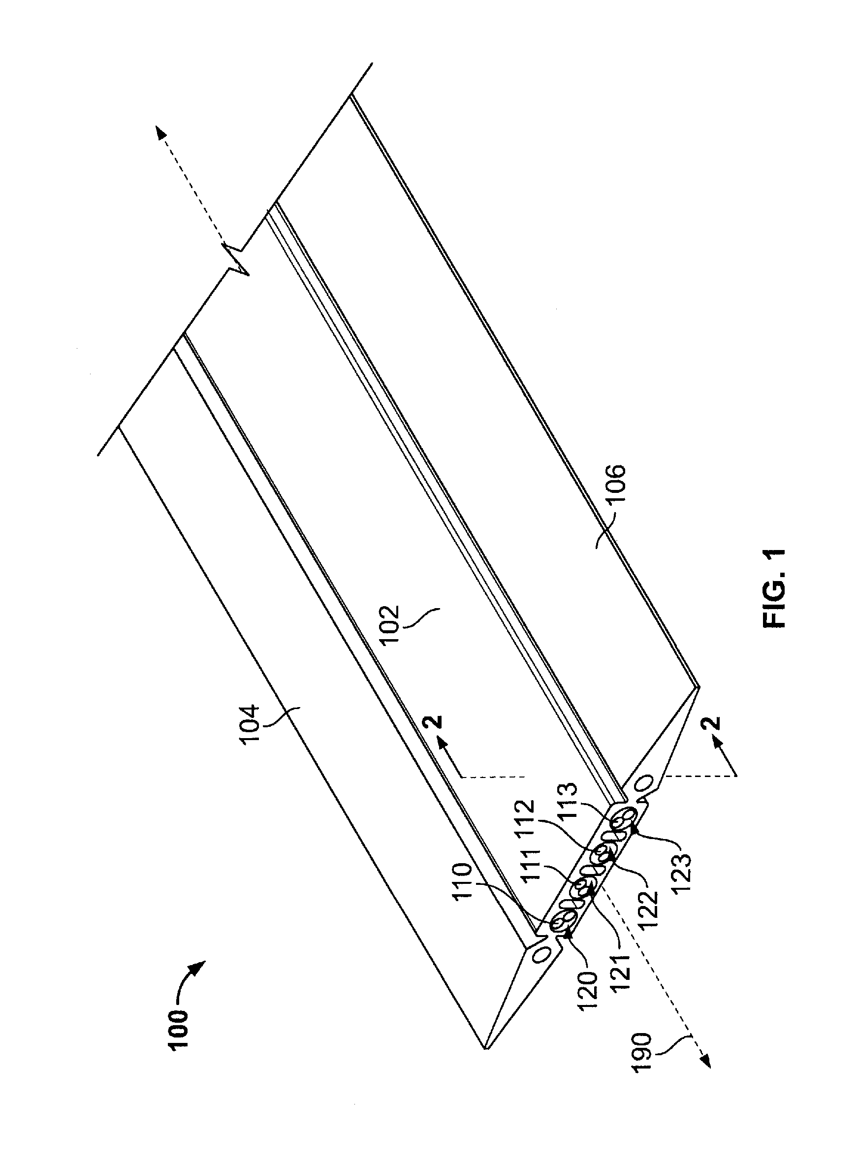
[0016]FIG. 1 is a perspective view of a low-profile cable 100 formed in accordance with one embodiment. The cable 100 may be integrally formed from a dielectric material, such as polyvinyl chloride (PVC), during an extrusion process. The cable 100 may also be formed to include an elongated body 102 having a substantially rectangular cross section that extends lengthwise along a longitudinal axis 190. Alternatively, the body 102 may have other cross-sectional shapes, such as a rounded top or a substantially semi-circle shape. The body 102 includes a plurality of conductor passages 120-123 that are each configured to hole one or more conductors, which are illustrated in FIG. 1 as twisted pairs of conductors 110-113, respectively. Also, the cable 100 may include wing members 104 and 106 that project laterally outward from the body 102. The cable 100 shown in FIG. 1 may be used to transmit high speed electronic signals in a computer network, e.g., Ethernet, in areas or locations that re...


PUM


Abstract

A low-profile cable is provided and includes a body having upper and lower portions that extend a length of the body and also having opposite sidewalls joining the upper and lower portions to one another. The cable also includes passages that are located between the sidewalls. The passages extend the length of the body and are configured to receive at least one twisted pair of conductors. Also, the cable includes a load-bearing structural section that spans between the upper and lower portions. The structural section includes opposing wall supports separated by a pocket channel therebetween. The structural section is configured to support the upper and lower portions and substantially resist deformation of the passages when external forces are induced onto at least one of the upper and lower portions.

Description

BACKGROUND OF THE INVENTION[0001]The invention relates generally to electrical cables for transmitting signals, and more particularly to low-profile electrical cables that are subjected to compressive forces.[0002]In some network or telecommunication systems, electrical cables or wires must travel underneath carpeting or some other type of flooring. In these instances, a low-profile cable may be used. The low-profile cable generally includes an elongated rectangular body having a plurality of passages extending lengthwise therethrough. The passages are configured to hold one or more electrical conductors. While underneath the carpet or flooring, the cable may be subjected to external forces, such as from people walking over the cable and / or equipment rolling or resting over the cable. These compressive forces may move and / or damage the electrical conductors within the corresponding passages. Furthermore, if the electrical conductors form twisted pairs, the twisted relationship of th...

Claims


Application Information

Patent Timeline
IPC IPC(8): H01B11/02
CPCH01B7/0876H01B7/0823H01B11/02H01R12/00H02G3/0487
Inventor MARTIN, RALPH SYKESGENIAC, JOSEPH EDWARDSPEER, RICHARDGROMKO, MICHAEL THOMAS
Owner COMMSCOPE TECH LLC
Learn More