
Self-referencing biodetection method and patterned bioassays

a biodetection method and bioassay technology, applied in the field of self-referencing biodetection method and patterned bioassay, can solve the problems of reducing the number of usable reaction locations by half, and methods have yet to yield commercially available high-throughput instruments, so as to improve the ability to account and achieve accurate measurement

Inactive Publication Date: 2009-05-19
X BODY
View PDF118 Cites 28 Cited by
  • Summary
  • Abstract
  • Description
  • Claims
  • Application Information

AI Technical Summary

Benefits of technology

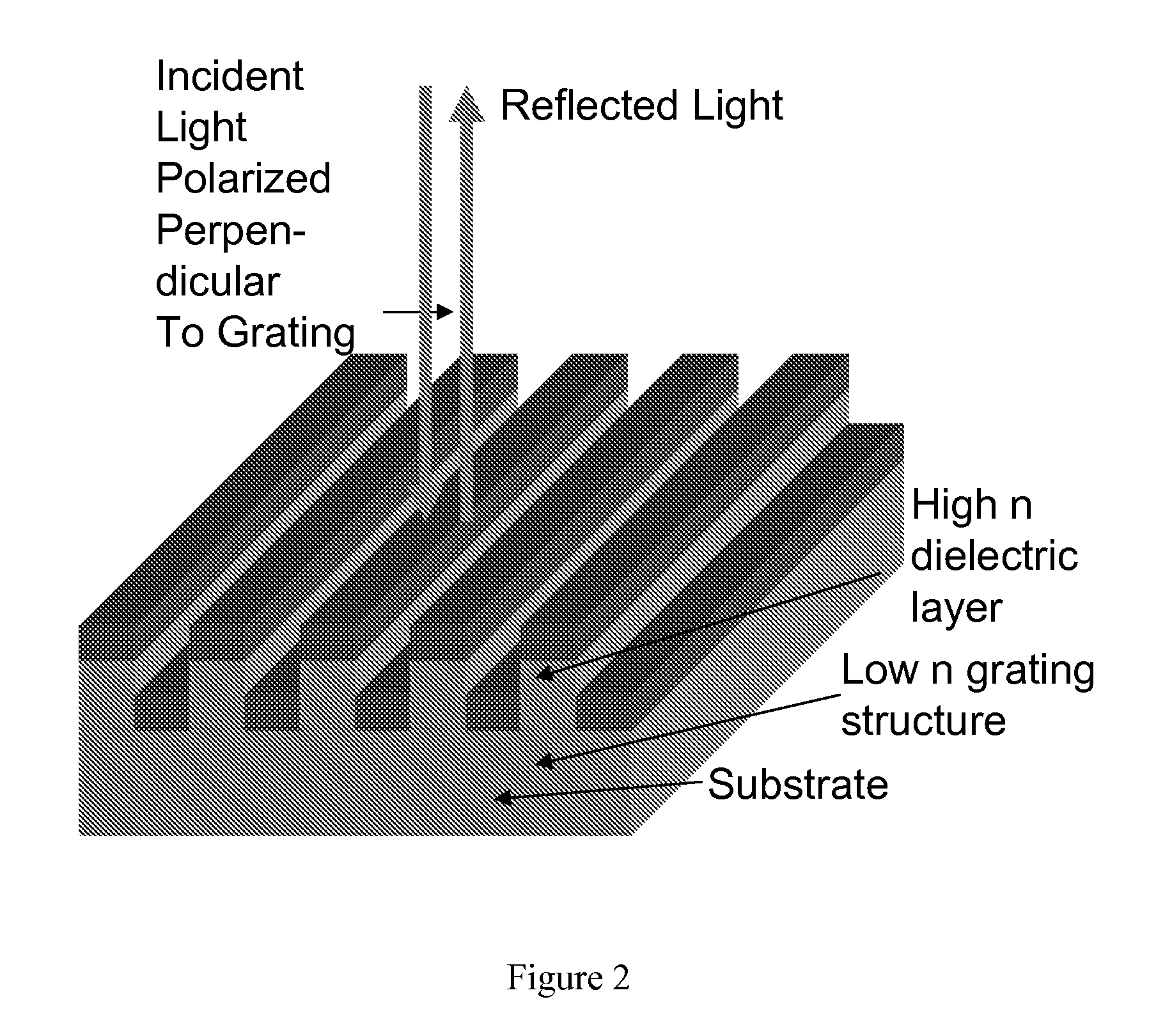
The patent describes a method for detecting the binding of specific substances to a colorimetric resonant optical biosensor. The biosensor has one or more reaction regions where the specific substances are immobilized, and one or more reference regions where they are not immobilized. When the biosensor is illuminated, a resonant grating effect is produced on the reflected radiation spectrum, and the depth and period of the grating of the biosensor can be measured. The method involves applying specific binding partners to the reaction regions and detecting the binding through the resonant grating effect. The invention provides a more sensitive and reliable method for detecting the binding of specific substances to the biosensor.

Problems solved by technology

With the completion of the sequencing of the human genome, one of the next grand challenges of molecular biology will be to understand how the many protein targets encoded by DNA interact with other proteins, small molecule pharmaceutical candidates, and a large host of enzymes and inhibitors.
However, to date, these methods have yet to yield commercially available high-throughput instruments that can perform high sensitivity assays without any type of label in a format that is readily compatible with the microtiter plate-based or microarray-based infrastructure that is most often used for high-throughput biomolecular interaction analysis.
Furthermore, detection of small molecules with low affinities and low concentrations requires the measurement of signals that are near the noise resolution limit of the above instruments.
While separate reference reactions can be used to compensate for the aberrant signal changes, such compensation tactics reduce the number of usable reaction locations by one half.

Method used


Image

  • Self-referencing biodetection method and patterned bioassays
  • Self-referencing biodetection method and patterned bioassays
  • Self-referencing biodetection method and patterned bioassays

Examples


example 1

Control of Molecular Surface Pattern

[0186]This example demonstrates control of a molecular surface pattern that is generated by a biomolecular cleavage event. Selected regions of a colorometric resonant optical biosensor embedded within the bottom of a 7 mm diameter microtiter well were treated with a NHS-PEG-biotin solution (Shearwater), the specific binding substance, by applying stripes of specific binding substance with a micropipette tip. The specific binding substance solution was allowed to incubate on the biosensor surface for about 20 minutes before thorough rinsing with water. Following rinsing, the microtiter well was filled with a 1 mg / ml solution of NHS-PEG (Shearwater), which was allowed to incubate in the well for an about 20 minutes. NHS-PEG blocks nonspecific binding of proteins to the biosensor surface. After an additional thorough rinsing with water, a 1 mg / ml solution of streptavidin-Cy5 (Molecular Probes), the specific binding partner, was introduced to the well...

example 2

Arbitrary Biosensor Surface Patterning

[0189]This example demonstrates the ability to generate an arbitrary binding pattern through the application of a specific binding substance to the colorometric resonant optical biosensor surface. A pattern of gelatin (1 mg / ml, Sigma) was applied to a biosensor with a micropipette tip in the shape of the letters “SRU.” The gelatin was allowed to incubate on the biosensor surface for about 60 minutes before a thorough rinse with water. Next, the entire biosensor surface was exposed to a 1 mg / ml solution of rabbit IgG (Sigma) that attached a uniform thin layer of protein across the biosensor so that the peak wavelength value of the biosensor would be roughly equivalent in all locations. After a second rinse in water, the entire biosensor was exposed to a 1.5 mg / ml solution of collagenase, a specific binding partner, for about 80 minutes. The collagenase is an enzyme that selectively cleaves gelatin, thus selectively removing protein from the surfa...

example 3

Experiment Setup

[0190]Plate—96-well biosensor microplate with a central line of UV curable adhesive drawn in the wells by an automated liquid dispensing instrument.

[0191]Instrument Setup—Instrument was set up to read 2 spots per well. Each spot was offset from the well center by ±2 mm.

[0192]DMSO Concentration Series—A DMSO concentration series of 5% DMSO, 1% DMSO, 0.5% DMSO, and 0.1% DMSO in PBS was added to individual wells of a 96-well biosensor microplate.

[0193]Initial reading. An initial measurement was made to observe the baseline peak wavelength shift over time in the neat wells. Each well contained 90 μL PBS and was read on each side of the barrier. Results are shown in FIG. 11. Baseline drift measurements and peak shape / height read on either side of the well are equivalent.

[0194]DMSO reading. DMSO was added to the wells to create a bulk shift response (as a result of DMSO's higher refractive index) in order to compare responses obtained on the right and left sides of each we...


PUM

PropertyMeasurementUnit
thicknessaaaaaaaaaa
grating periodaaaaaaaaaa
grating depthaaaaaaaaaa

Abstract

The invention relates to compositions and methods for detecting biomolecular interactions. The detection can occur without the use of labels and can be done in a high-throughput manner. The invention further relates to self-referencing colorimetric resonant optical biosensors and optical devices.

Description

PRIORITY[0001]This application is a divisional application of U.S. Ser. No. 10 / 727,680, filed Dec. 4, 2003 (allowed), which claims the benefit of U.S. provisional application Ser. No. 60 / 430,911, filed Dec. 4, 2002. These applications are herein incorporated by reference in their entirety.TECHNICAL AREA OF THE INVENTION[0002]The invention relates to methods for detecting biomolecular interactions. The detection can occur without the use of labels and can be done in a high-throughput manner. The invention further relates to self-referencing colorimetric resonant optical biosensors. The invention also relates to optical devices.BACKGROUND OF THE INVENTION[0003]With the completion of the sequencing of the human genome, one of the next grand challenges of molecular biology will be to understand how the many protein targets encoded by DNA interact with other proteins, small molecule pharmaceutical candidates, and a large host of enzymes and inhibitors. See e.g., Pandey & Mann, “Proteomic...

Claims


Application Information

Patent Timeline
Patent Type & Authority Patents(United States)
IPC IPC(8): G01N33/573G01N33/551
CPCG01N21/7703G01N33/54373G01N21/78Y10S435/808Y10S436/807Y10S436/805G01N2021/7779
Inventor BAIRD, CHERYLCUNNINGHAM, BRIAN T.LI, PETER
Owner X BODY
Learn More