
RF MEMS series switch using piezoelectric actuation and method of fabrication

a piezoelectric and actuation technology, applied in the field of microelectronic systems, can solve the problems of bulk silicon micromachining, integration with other fabrication technologies, and the tendency of piezoelectric mems to outperform electrostatic mems,

Inactive Publication Date: 2009-05-12
UNITED STATES OF AMERICA THE AS REPRESENTED BY THE SEC OF THE ARMY
View PDF13 Cites 15 Cited by
  • Summary
  • Abstract
  • Description
  • Claims
  • Application Information

AI Technical Summary

Problems solved by technology

However, piezoelectric MEMS tend to out-perform electrostatic MEMS actuators in out-of-plane (vertical) displacements in terms of attainable range, power consumption, and voltage level.
However, this design utilizes bulk silicon micromachining which is generally regarded as an expensive fabrication process in the industry and typically has difficulty being integrated with other fabrication technologies.

Method used


Image

  • RF MEMS series switch using piezoelectric actuation and method of fabrication
  • RF MEMS series switch using piezoelectric actuation and method of fabrication
  • RF MEMS series switch using piezoelectric actuation and method of fabrication

Examples


Embodiment Construction

[0045]The embodiments herein and the various features and advantageous details thereof are explained more fully with reference to the non-limiting embodiments that are illustrated in the accompanying drawings and detailed in the following description. Descriptions of well-known components and processing techniques are omitted so as to not unnecessarily obscure the embodiments herein. The examples used herein are intended merely to facilitate an understanding of ways in which the embodiments herein may be practiced and to further enable those of skill in the art to practice the embodiments herein. Accordingly, the examples should not be construed as limiting the scope of the embodiments herein.

[0046]As mentioned, there remains a need for a new RF MEMS switch capable of being fabricated relatively easy and providing improved results in operation and increased uses of application. The embodiments herein achieve this by providing a RF MEMS series switch and method of fabrication that ov...


PUM


Abstract

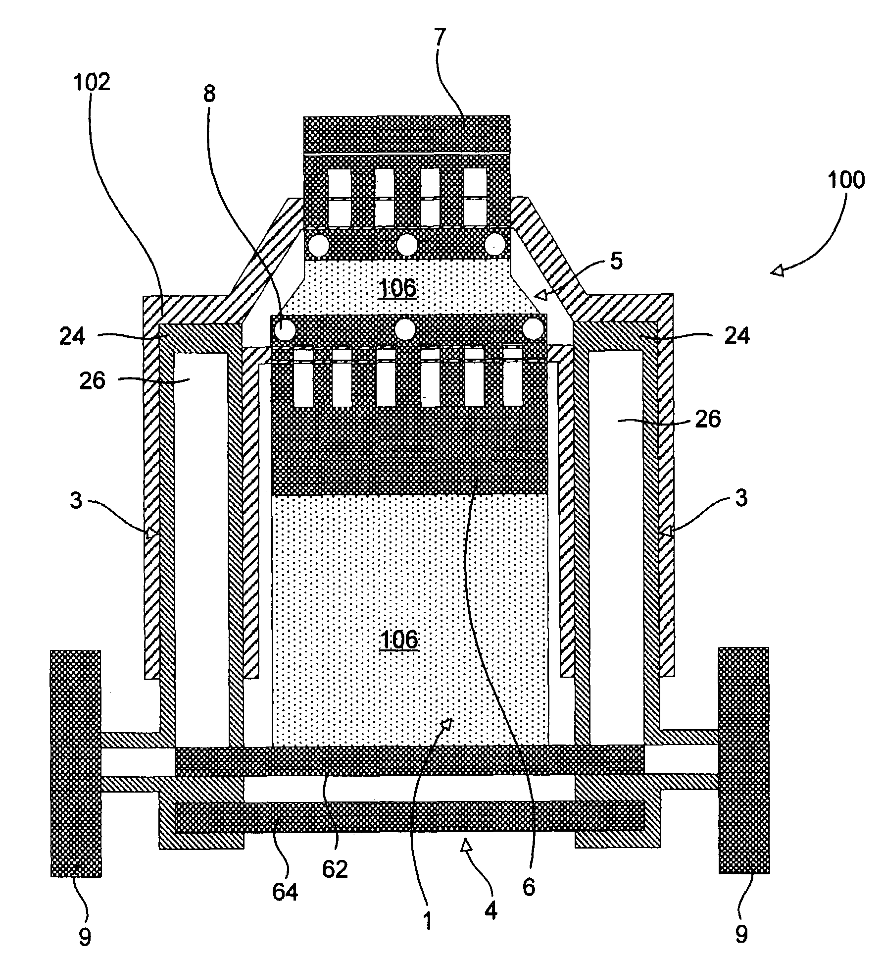
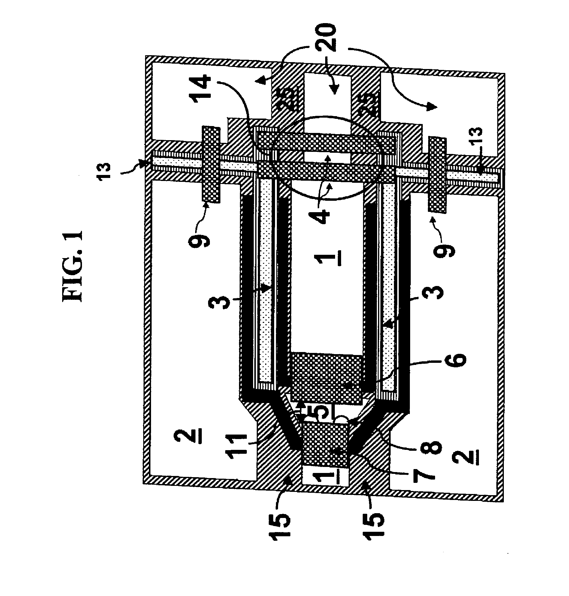
A microelectromechanical system (MEMS) switch comprising a radio frequency (RF) transmission line; a structurally discontinuous RF conductor adjacent to the RF transmission line; a pair of cantilevered piezoelectric actuators flanking the RF conductor; a contact pad connected to the pair of cantilevered piezoelectric actuators; a pair of cantilevered structures connected to the RF conductor; a plurality of air bridges connected to the pair of cantilevered piezoelectric actuators; and a plurality of contact dimples on the contact pad. Preferably, the RF transmission line comprises a pair of co-planar waveguide ground planes flanking the RF conductor; and a plurality of ground straps connected to the pair of co-planar waveguide ground planes, wherein the RF transmission line is operable to provide a path along which RF signals propagate.

Description

CROSS-REFERENCE TO RELATED APPLICATIONS[0001]This application is a continuation-in-part of U.S. patent application Ser. No. 11 / 347,291 filed Feb. 6, 2006, the complete disclosure of which, in its entirety, is herein incorporated by reference.GOVERNMENT INTEREST[0002]The embodiments described herein may be manufactured, used, and / or licensed by or for the United States Government without the payment of royalties thereon.BACKGROUND[0003]1. Technical Field[0004]The embodiments herein generally relate to microelectronic systems, and more particularly, to radio frequency (RF) microelectromechanical systems (MEMS) and piezoelectric MEMS actuation technology and microelectronics.[0005]2. Description of the Related Art[0006]MEMS devices are micro-dimensioned machines manufactured by typical integrated circuit (IC) fabrication techniques. The relatively small size of MEMS devices allows for the production of high speed, low power, and high reliability mechanisms. The fabrication techniques a...

Claims


Application Information

Patent Timeline
IPC IPC(8): H01P1/10H01H57/00
CPCH01H57/00H01P1/127H01H2057/006
Inventor PULSKAMP, JEFFREY S.POLCAWICH, RONALD G.JUDY, DANIEL
Owner UNITED STATES OF AMERICA THE AS REPRESENTED BY THE SEC OF THE ARMY
Learn More