
Automotive construction machine, as well as method for working ground surfaces

a construction machine and motor technology, applied in the direction of manufacturing tools, working accessories, roads, etc., can solve the problems of affecting the operation of the machine operator, the milling drum being damaged, and the construction machine being accelerated suddenly and uncontrollably

Active Publication Date: 2009-05-12
WIRTGEN AMERICA
View PDF10 Cites 45 Cited by
  • Summary
  • Abstract
  • Description
  • Claims
  • Application Information

AI Technical Summary

Benefits of technology

"The invention is about an improved automotive construction machine for working ground surfaces. The machine has a milling drum that can be raised and lowered to perform different tasks. The problem with previous machines is that it took a long time to stop and start the engine and drive the wheels or crawler tracks. This was annoying for the operator and caused wear and tear on the components. The invention solves this problem by allowing the milling drum to remain coupled with the drive engine in a permanent manner, so that it doesn't need to be uncoupled when raised. This reduces the time required for each task and also reduces the wear and tear on the machine's components. The machine can travel in both forward and backward direction, and the milling drum can remain coupled with the drive engine even when traveling backwards."

Problems solved by technology

It is necessary that the milling drum is idle when traveling backwards in order to avoid any accidental collision of the tools of the milling drum with the ground surface, because the construction machine may be accelerated suddenly and uncontrollably in case of an inadvertent engagement of the milling drum with the ground surface.
This results in a risk of the milling drum being damaged in case of an accidental engagement with the ground surface, so that the milling drum is first uncoupled from the drive train after it has been raised from the milled cut at the end of a ground surface to be worked.
These processes are very time-consuming and very annoying for the machine operator, in particular in case of short stretches of road to be worked.
Moreover, the incessant switching operations of the coupling and the related frequent load changes of the combustion engine give rise to increased wear and tear of the coupling, the combustion engine and all components that are part of the drive train.

Method used


Image

  • Automotive construction machine, as well as method for working ground surfaces
  • Automotive construction machine, as well as method for working ground surfaces
  • Automotive construction machine, as well as method for working ground surfaces

Examples


Embodiment Construction

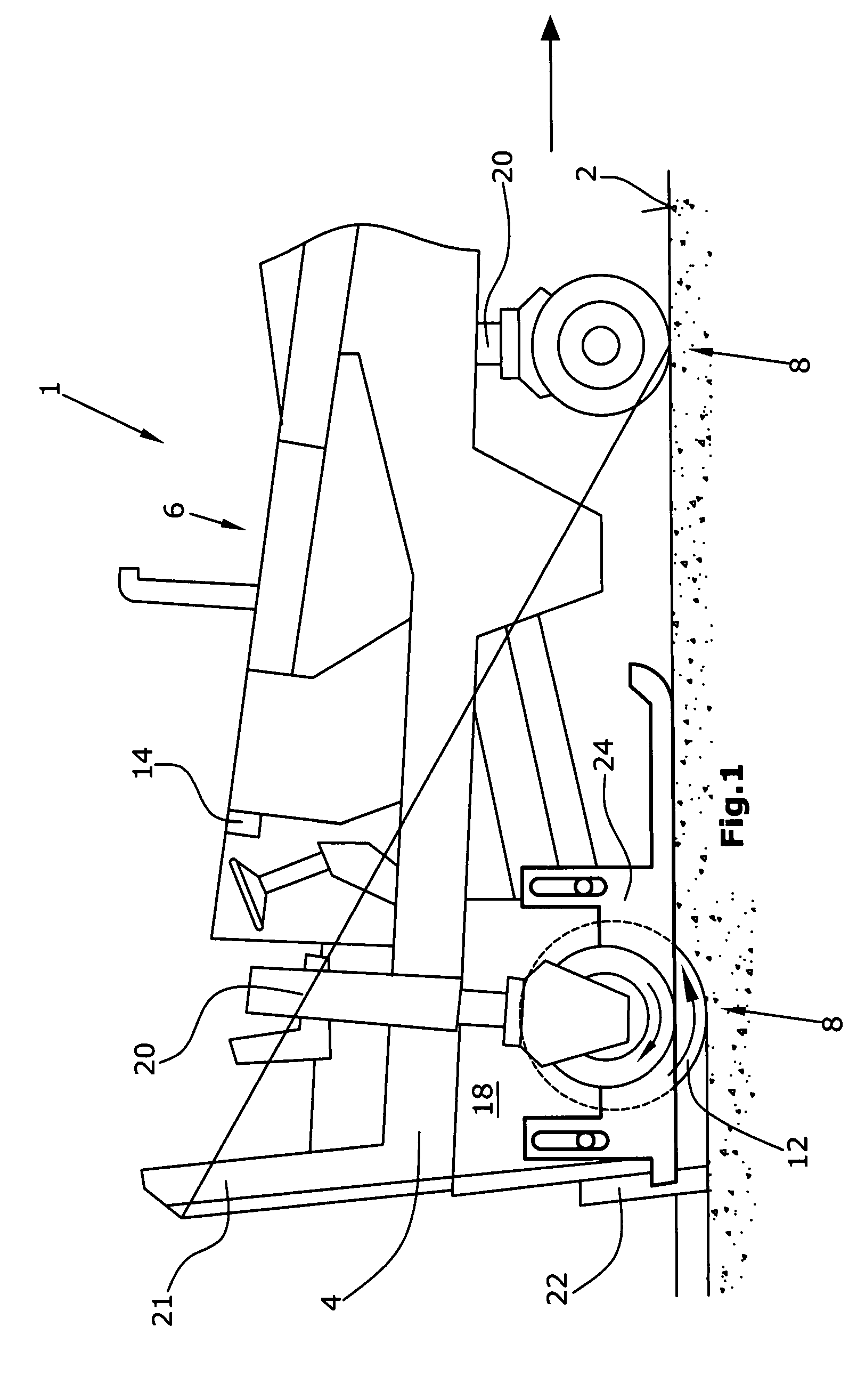
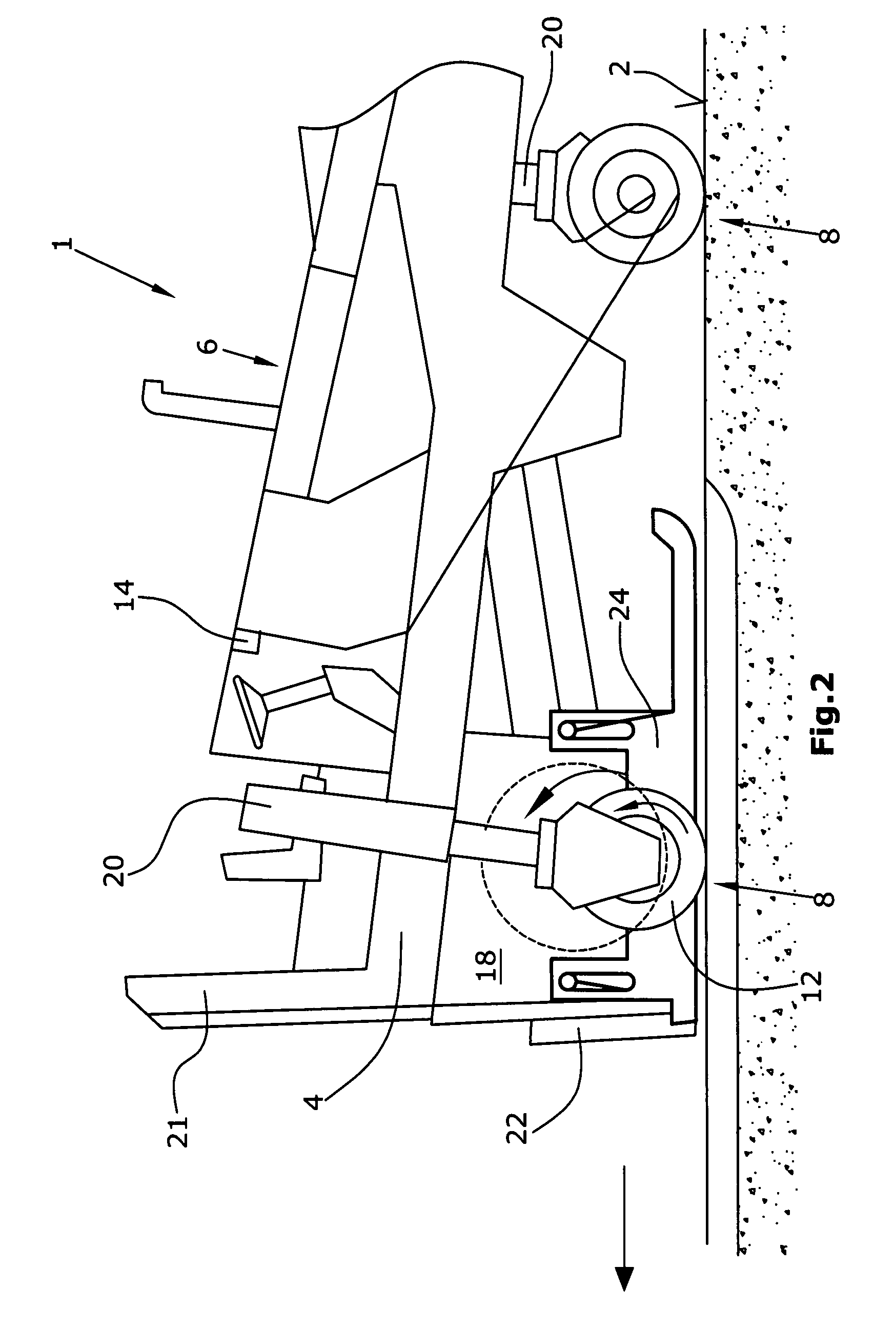
[0034]The automotive construction machine 1 for working ground surfaces 2 shown in FIG. 1 shows a machine frame 4, as well as a drive engine 6 for driving traveling devices 8 and for driving working devices. In the embodiment in FIG. 1, the traveling devices 8 consist of wheels, whereas in the embodiment in FIG. 3, the said traveling devices 8 consist of crawler track units. The main working device consists of a milling drum 12 for milling the ground surface 2, where the said milling drum 12 is capable of being driven by a drum drive 10 and of being uncoupled from the drive engine 6.

[0035]The milling drum is capable of being moved into a raised position when it is not in milling mode.

[0036]The raised position of the milling drum 12 is preferably achieved by means of the lifting columns 20, by way of raising the machine frame 4 altogether. In doing so, the milling drum 12, which is supported in the machine frame 4, is raised out of the milled track until it shows a pre-determined dis...


PUM

PropertyMeasurementUnit
distanceaaaaaaaaaa
travel speedaaaaaaaaaa
heightaaaaaaaaaa

Abstract

An automotive construction machine for working ground surfaces, with a machine frame, a drive engine for driving traveling devices and for driving working devices, and a milling drum for milling the ground surfaces, which can be raised, driven by, and can be uncoupled from a drum drive, the milling drum can be moved into a raised position when not in milling mode, and when raised, the rotating direction of the milling drum corresponds to the rotating direction of the traveling devices and remains coupled with the drive engine, and a monitoring device monitors the distance between the milling drum and the ground surface and uncouples the raised milling drum from the drive engine or uncouples the traveling devices from the drive engine or raises the machine frame or generates an alarm signal when the monitoring device detects a deviation that falls below a pre-determined distance, or any of the latter.

Description

BACKGROUND OF THE INVENTION[0001]The invention concerns an automotive construction machine, as well as a method for working ground surfaces.[0002]Such automotive construction machines for working ground surfaces are known, for instance, from EP 1408158 A.[0003]The road milling machine described therein shows a machine frame with a drive engine for driving traveling devices and for driving working devices. The traveling devices may consist of either wheels or crawler tracks, which are connected to the machine frame via lifting columns.[0004]A drum drive drives a milling drum for milling the ground surfaces preferably in up-milling mode. The milling drum is capable of being uncoupled from the drive train by means of a coupling. A scraper blade is located in a height-adjustable manner behind the milling drum when seen in the direction of travel, which can glide on the surface milled or to be milled by the milling drum. In milling mode, the lower edge of the scraper blade is always loca...

Claims


Application Information

Patent Timeline
Patent Type & Authority Patents(United States)
IPC IPC(8): E01C23/088
CPCB28D1/18B28D7/005E01C23/088E02F3/783E02F3/8155
Inventor BERNING, CHRISTIANLANGE, HERBERTSIMONS, DIETER
Owner WIRTGEN AMERICA
Learn More