
Dyes for anisotropic dye films, dye compositions for anisotropic dye films, anisotropic dye films and polarizing elements

a dye film and anisotropic technology, applied in the direction of polarizing elements, polyazo dyes, instruments, etc., can solve the problems of insufficient heat resistance and light fastness, inability to obtain ideal achromatic color polarizing plates for the entire visible spectral region, and insufficient dichromatic properties, etc., to achieve excellent heat resistance, light fastness and polarizing performance, and high dichromatic properties

Inactive Publication Date: 2009-05-05
MITSUBISHI CHEM CORP
View PDF33 Cites 10 Cited by
  • Summary
  • Abstract
  • Description
  • Claims
  • Application Information

AI Technical Summary

Benefits of technology

[0017]It is an object of the present invention to provide anisotropic dye films having high dichromatic properties, and polarizing elements excellent in heat resistance, light fastness and polarizing performance, employing the anisotropic dye films. Further, it is an object of the present invention to provide novel dichroic dyes and dye compositions for anisotropic dye films, with which anisotropic dye films which function as anisotropic dye films having heat resistance and light fastness, can be realized.
[0018]As a result of extensive studies, the present inventors have found that an anisotropic dye film having high dichromatic properties can be securely realized by specifying crystal structure parameters of the anisotropic dye film and accomplished the present invention.
[0020]Further, the present inventors have found that as a novel dichroic azo dye, a dichroic azo dye having a specific structure, having a triazinyl group and having at least three azo couplings in one molecule, represented by the following formula (1), has high affinity with a substrate. Further, they have found that by forming a film by using a composition containing such a dye by means of a wet film-forming method, the dichroic dye molecules show a high-level molecular orientation state, that is, a dye film having high anisotropy can be formed.
[0026]The present inventors have further found that by employing an azo dye represented by the following formula (2), an anisotropic dye film formed by a wet film-forming method is achromatic, has high dichromatic properties and shows a high degree of molecular orientation.

Problems solved by technology

Further, iodine has high sublimation properties and accordingly when it is used for a polarizing plate, the heat resistance and the light fastness are insufficient.
Further, the extinction color becomes dark grayish blue, and an ideal achromatic color polarizing plate for the entire visible spectral region can not necessarily obtained.
For applications as a polarizing element, in order to obtain higher polarizing performance, an anisotropic dye film having high dichromatic properties has been required, however, such a conventional anisotropic dye film is poor in dichromatic properties, and accordingly no polarizing element excellent in polarizing performance can be obtained.
However, the compounds as disclosed in the above JP-A-3-12606 and JP-A-1-161202 have insufficient dichromatic properties, and particular the compound as disclosed in JP-A-3-12606 has a low solubility in various solvents.
Accordingly, it can not be said that they are sufficient as a material of an anisotropic dye film to be produced by a wet film-forming method.
However, the above compounds are both disazo compounds, and their dichromatic properties and solubility in a solvent are insufficient as a material of an anisotropic dye film to be produced by a wet film-forming method.
However, the above compound is a disazo compound and has a halogen atom bonded on the triazine ring, whereby it is likely to decompose.

Method used


Image

  • Dyes for anisotropic dye films, dye compositions for anisotropic dye films, anisotropic dye films and polarizing elements
  • Dyes for anisotropic dye films, dye compositions for anisotropic dye films, anisotropic dye films and polarizing elements
  • Dyes for anisotropic dye films, dye compositions for anisotropic dye films, anisotropic dye films and polarizing elements

Examples


example 1

[0245]10 Parts of the following exemplified dye No. (I-31) and 0.2 part of a nonionic surfactant EMULGEN 109P (manufactured by Kao Corporation) were dissolved in 89.8 parts of water with stirring to obtain a dye composition for an anisotropic dye film:

[0246]

[0247]On the other hand, a substrate comprising a glass substrate (75 mm×25 mm, thickness 1 mm) and a polyimide alignment film formed thereon by silk printing (polyimide film thickness: about 800 Å), which was preliminarily subjected to rubbing treatment with cloth, was prepared. The dye composition for an anisotropic dye film was coated on the substrate thus prepared by a bar coater (“No. 3” manufactured by TESTER SANGYO CO., LTD.), followed by air drying to obtain an anisotropic dye film having a film thickness of about 0.4 μm.

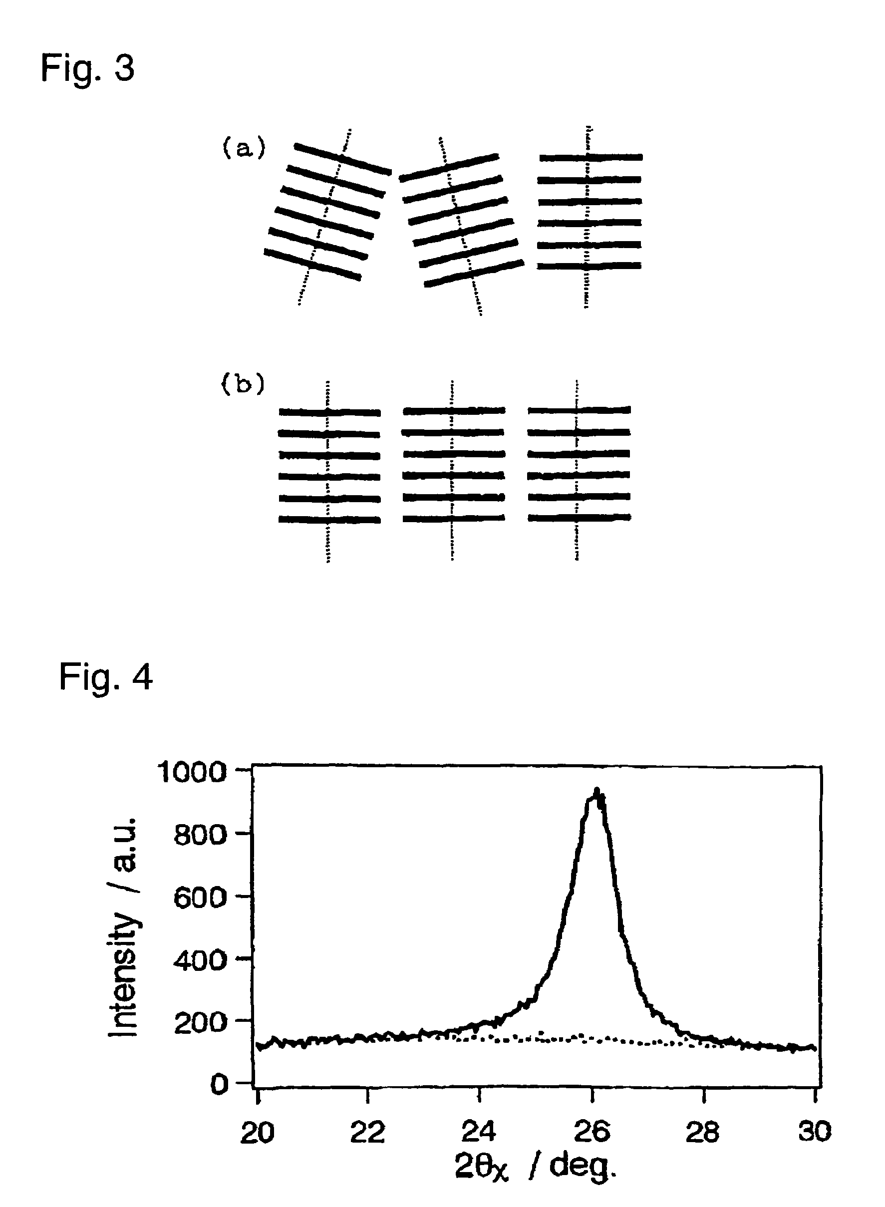
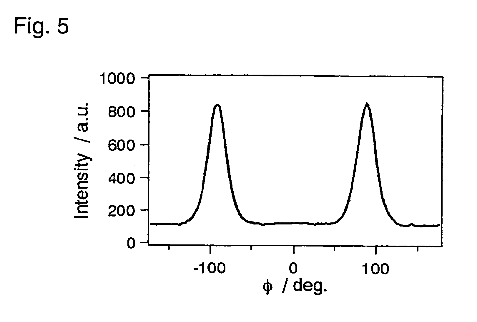
[0248]The X-ray diffraction profile and the in-plane rocking profile of the obtained anisotropic dye film are shown in FIG. 4 and FIG. 5, respectively. FIG. 4 illustrates the result of the in-plane measur...

example 2

[0251]10 Parts of the following exemplified dye No. (II-15) was dissolved in 90 parts of water with stirring to obtain a dye composition for an anisotropic dye film:

[0252]

[0253]In the same manner as in Example 1 except that a bar coater (“No. 2” manufactured by TESTER SANGYO CO., LTD.) was used, the dye composition for an anisotropic dye film was coated on a glass substrate having a polyimide alignment film formed thereon, followed by air drying to obtain an anisotropic dye film.

[0254]The molecular stacking period, the column length, the degree of orientation of the molecular stacking axes and the dichroic ratio of the obtained anisotropic dye film were examined and the results are shown in Table 1.

[0255]It was confirmed from Table 1 that the anisotropic dye film of the present Example has a molecular alignment suitable to develop the dichroic ratio, and has a high dichroic ratio.

example 3

[0256]8 Parts of the following exemplified dye No. (I-1) was dissolved in 92 parts of water with stirring to obtain a dye composition for an anisotropic dye film:

[0257]

[0258]In the same manner as in Example 1 except that an applicator with a gap of 10 μm (manufactured by Imoto Machinery Co., Ltd.) was used, the dye composition for an anisotropic dye film was coated on a glass substrate having a polyimide alignment film formed thereon, followed by air drying to obtain an anisotropic dye film.

[0259]The molecular stacking period, the column length, the degree of orientation of the molecular stacking axes and the dichroic ratio of the obtained anisotropic dye film were examined, and the results are shown in Table 1.

[0260]It was confirmed from Table 1 that the anisotropic dye film of the present Example has a molecular alignment suitable to develop the dichroic ratio, and has a high dichroic ratio.


PUM

PropertyMeasurementUnit
thicknessaaaaaaaaaa
molecular column lengthaaaaaaaaaa
thicknessaaaaaaaaaa

Abstract

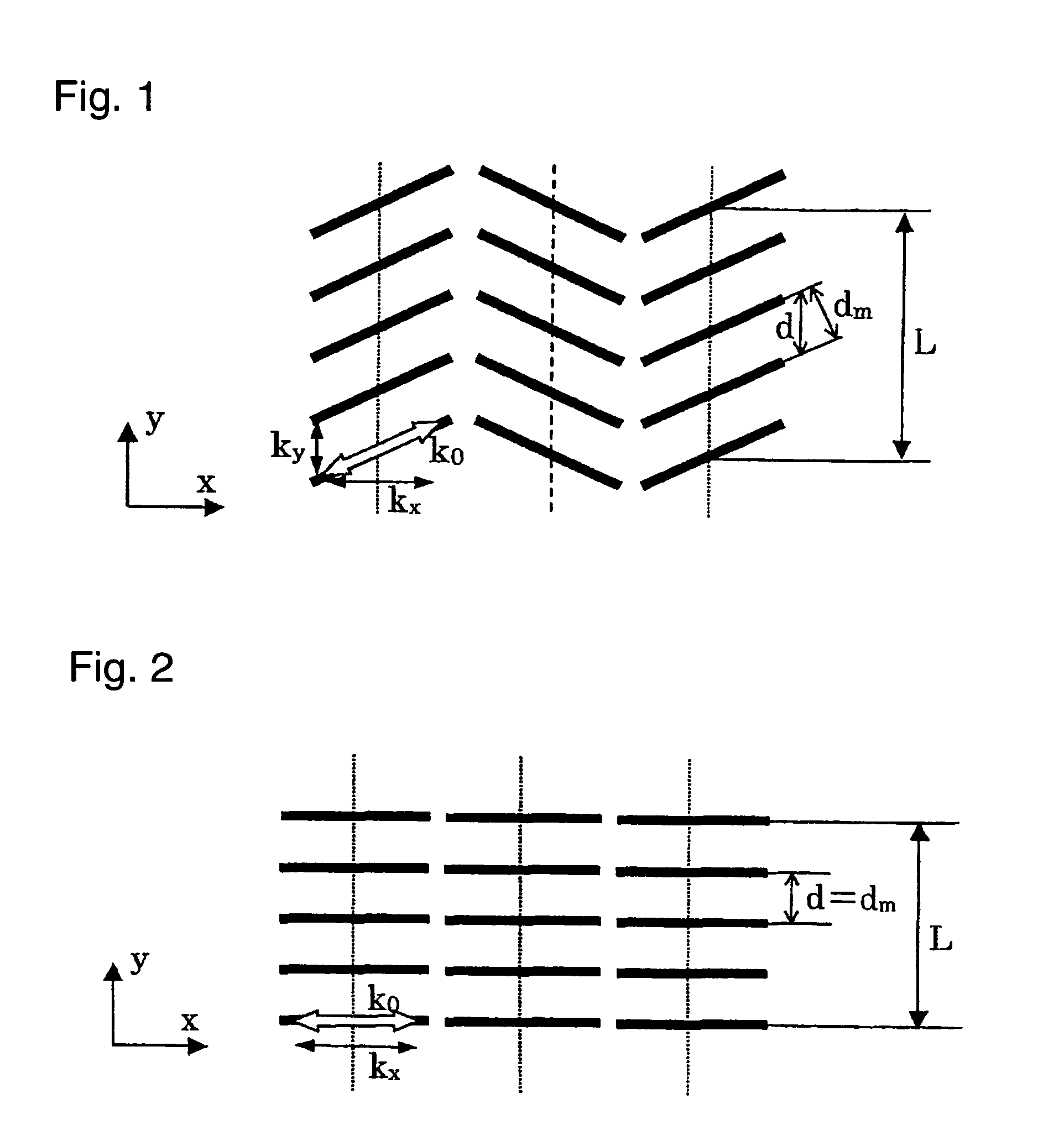
An anisotropic dye film having high dichromatic properties is provided.An anisotropic dye film wherein the period d attributable to molecular stacking is at most 3.445 Å, and the column length L thereof is at least 105 Å. The anisotropic dye film preferably has a degree of orientation of the molecular stacking axes of at least 85% and a film thickness of at most 30 μm, and is formed by a wet film-forming method. Since it has a molecular alignment suitable to develop a dichroic ratio, it provides high dichromatic properties. A polarizing element having this anisotropic dye film is excellent in heat resistance, light fastness and polarizing performance.

Description

TECHNICAL FIELD[0001]The present invention relates to anisotropic dye films having high dichromatic properties, useful for e.g. a polarizing plate to be used for a light control device, a liquid crystal device and a display device of an organic electroluminescence device (OLED), polarizing elements employing the anisotropic dye films, and dye compositions for anisotropic dye films to obtain the anisotropic dye films. Further, the present invention relates to novel azo dyes useful for anisotropic dye films.BACKGROUND ART[0002]For LCD (liquid crystal display), a linear polarizing plate or a circular polarizing plate is employed to control the optical rotation and birefringence in display. For OLED also, a circular polarizing plate is used to prevent reflection of external light.[0003]Heretofore, for such a polarizing plate, an anisotropic dye film obtained in such a manner that iodine or an organic dye having dichromatic properties is dissolved or adsorbed in a polymer material such a...

Claims


Application Information

Patent Timeline
Patent Type & Authority Patents(United States)
IPC IPC(8): B32B9/04C09B31/22C09B31/30C09B43/16C09K19/60G02B5/30
CPCC09B31/22C09B31/30C09B43/16G02B5/3025G02B5/3083C09K19/601Y10T428/1041Y10T428/31786Y10T428/31855Y10T428/31725Y10T428/31504C09K2323/031C09B31/20C09K19/60G02B5/30
Inventor YONEYAMA, TOMIOHASEGAWA, RYUICHISANO, HIDEOOIZUMI, JUNICHINISHIMURA, MASAAKIKADOWAKI, MASAMI
Owner MITSUBISHI CHEM CORP
Learn More