Eureka AIR delivers breakthrough ideas for toughest innovation challenges, trusted by R&D personnel around the world.

Fiber-reinforced, porous, biodegradable implant device

a biodegradable, fiber-reinforced technology, applied in the direction of prosthesis, joint implants, other domestic articles, etc., can solve the problem that no evidence is presented to verify that the mechanical properties are actually improved, and achieve the effect of facilitating the regeneration of load-bearing tissues

Inactive Publication Date: 2009-04-28
OSTEOBIOLOGICS
View PDF105 Cites 23 Cited by
  • Summary
  • Abstract
  • Description
  • Claims
  • Application Information

AI Technical Summary

Benefits of technology

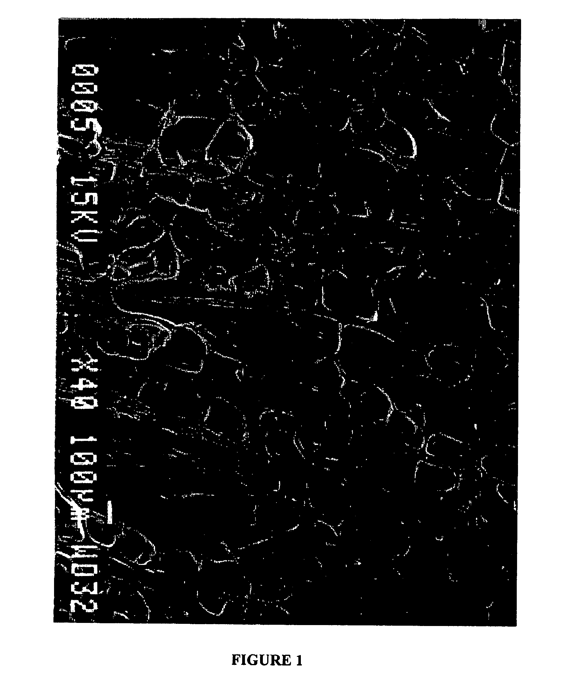
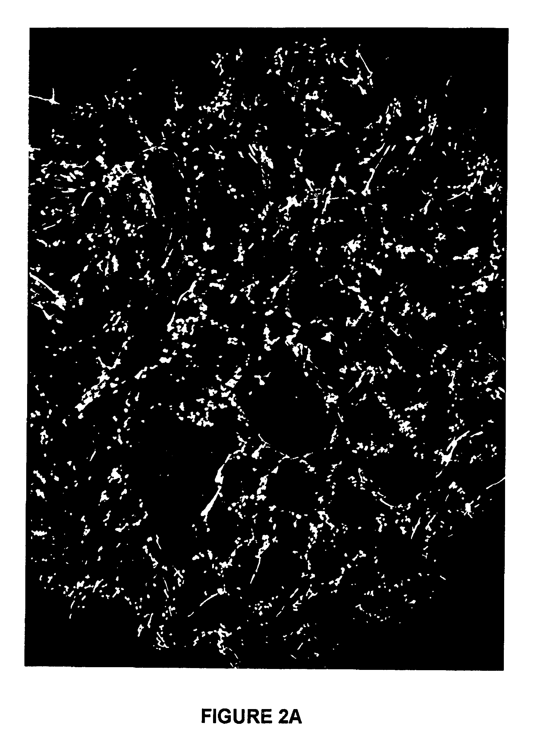
[0007]This invention provides a fiber-reinforced, polymeric implant material useful for tissue engineering, and method of making same. The implant material preferably comprises a polymeric matrix, preferably a biodegradable matrix, having fibers substantially uniformly distributed therein in predominantly parallel orientation as shown in FIGS. 1 and 2. In an embodiment, the implant further comprises inorganic particles. In preferred embodiments, porous tissue scaffolds are provided which facilitate regeneration of load-bearing tissues such as articular cartilage and bone.
[0008]The material of this invention is used to prepare porous, fiber-reinforced, biodegradable tissue scaffolds whose fibrous supports are oriented predominantly in a single direction. The scaffold may be implanted into humans or animals to provide support for physiological loads applied parallel to the predominant direction of orientation of the fibers. For example, in an osteochondral site on the femoral condyle, the primary direction of loading is perpendicular to the surface of the cartilage. The oriented fibers act like struts in a bridge support to provide strength and stiffness to the pore walls of the scaffold and provide a characteristic columnar pore architecture especially suitable for cell ingrowth. The orientation of the fibers also causes the mechanical properties of the scaffold to be anisotropic, i.e., the higher strengths provided by the fibers is maximal in the direction parallel to the fibers, thus providing primary support for physiological loads where they are highest.
[0009]Orientation of the fibers is achieved through a dissolution-precipitation process combined with a novel kneading and rolling process. Using various amounts of fiber reinforcement, the mechanical properties of the scaffold may be tailored to the host tissue environment for optimal performance.

Problems solved by technology

Although the fibers are incorporated to “reinforce” the scaffold, no evidence is presented to verify that the mechanical properties are actually improved through such reinforcement and the fibers appear to be randomly aligned.

Method used


Image

  • Fiber-reinforced, porous, biodegradable implant device
  • Fiber-reinforced, porous, biodegradable implant device
  • Fiber-reinforced, porous, biodegradable implant device

Examples


example 1

Method of Producing a 10% Chopped PGA Fiber-Reinforced, Porous, Biodegradable Implant

[0064]To manufacture a 70 volume % porous, 10 volume % chopped PGA fiber-reinforced, 75:25 poly(D,L-lactide-co-glycolide) (D,L-PLG) wafer, the following procedure was used. First, 1.38 g of 75:25 D,L-PLG (Mw=95,000 Da, intrinsic viscosity=0.76) was dissolved in a Teflon beaker using 6.2 mL of acetone. Next, 0.153 g of PGA fibers with a diameter of approximately 15 cm, chopped to an average length of about 2.6 mm, were placed in a scintillation vial. Then, 6.2 mL of ethanol was added to the vial with the fibers. The level of fluid in the vial was marked with a permanent marker. Next, the fibers and ethanol were transferred to a Waring blender with an additional 20 mL of ethanol. The mixture was blended on setting 2 for a period of 1 minute. The fiber and ethanol mixture was then added back into the scintillation vial, and the ethanol was decanted until the height of the mixture decreased to the marke...

example 2

Mechanical Testing to Show the Influence of Fiber Orientation on the Mechanical Properties of Porous, Biodegradable Implants

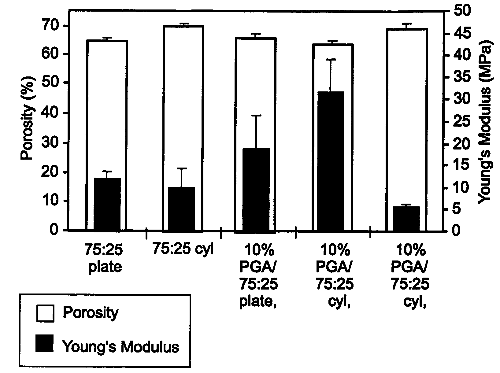
[0068]To make porous wafers with reinforcing fibers oriented preferentially in one direction, the manufacturing method described in the detailed description of the preferred embodiments and Example 1 was used. The addition “cyl” is attached to those implants made using this method, to indicate the cylindrical molds that were used. To make implants with reinforcing fibers oriented in two directions, a plate-like mold was used with dimensions 6 cm×6 cm×3 mm thick and the gel was flattened to fit the sides of the mold before the final vacuum step. The addition “flat” is attached to the implants made using this method, and indicates the flat, plate-like form of the cured wafer.

[0069]The matrix polymer used was a random copolymer of 75:25 poly(D,L-lactide-co-glycolide) and the fibers were poly(glycolide) with a diameter of about 15 μm and an average length of about ...

example 3

Mechanical Testing to Show the Influence of Increasing Levels of Chopped PGA Fiber-Reinforcement on Porous, Biodegradable Implants

[0079]Implants were made according to the method described in the detailed description of embodiments and in Example 1. The matrix polymer used was a random copolymer of 75:25 poly(D,L-lactide-co-glycolide) and the fibers were poly(glycolide) with a diameter of about 15 μm and an average length of about 2.5 mm. Implants were made with fiber volume fractions of 0%, 5%, 10%, 15%, and 20%. Cylindrical samples of about 6 mm diameter and 3 mm length were prepared according to the description in Example 1. The parallel plate compression test method described in Example 2 was used to measure the mechanical properties of the cylindrical wafers. The wafers were tested parallel to the direction of preferential orientation of the fibers.

[0080]From the stress versus strain data and postprocessing analysis, the Young's modulus and yield stress of the samples were comp...


PUM

PropertyMeasurementUnit
lengthaaaaaaaaaa
sizeaaaaaaaaaa
sizeaaaaaaaaaa

Abstract

A fiber-reinforced, polymeric implant material useful for tissue engineering, and method of making same are provided. The fibers are preferably aligned predominantly parallel to each other, but may also be aligned in a single plane. The implant material comprises a polymeric matrix, preferably a biodegradable matrix, having fibers substantially uniformly distributed therein. Inorganic particles may also be included in the implant material. In preferred embodiments, porous tissue scaffolds are provided which facilitate regeneration of load-bearing tissues such as articular cartilage and bone. Non-porous fiber-reinforced implant materials are also provided herein useful as permanent implants for load-bearing sites.

Description

CROSS-REFERENCE TO RELATED APPLICATIONS[0001]This application is continuation in part of U.S. application Ser. No. 10 / 288,400, filed Nov. 4, 2002 now U.S. Pat. No. 6,783,712, which is a divisional of U.S. application Ser. No. 09 / 426,686 filed 25 Oct. 1999 now U.S. Pat. No. 6,511,511, which claims priority to PCT Application PCT / US98 / 11007 filed 29 May 1998, which claims priority to U.S. Provisional Application No. 60 / 048,320 filed 30 May 1997, all of which are incorporated herein in their entirety to the extent they are not inconsistent herewith.BACKGROUND OF THE INVENTION[0002]The potential repair of articular cartilage in human using porous scaffolds has been described. Mears in U.S. Pat. No. 4,553,272 describes a method for osteochondral repair focusing on the use of starter cells, specific pore sizes in a porous scaffold, and providing a barrier between the two pore sizes. There is no mention of the use of biodegradable scaffolds or the necessity of providing a scaffold that can...

Claims


Application Information

Patent Timeline
Patent Type & Authority Patents(United States)
IPC IPC(8): A61F2/02A61F2/28A61F2/30A61F2/46A61L27/44A61L27/46A61L27/56A61L27/58B29C44/00B29C70/14B29D1/00C12N5/00
CPCA61F2/30756A61F2/30965A61L27/446A61L27/46A61L27/56A61L27/58B29C44/00B29C70/14A61F2/28A61F2/468A61F2002/30062A61F2002/30677A61F2002/30766A61F2210/0004B29K2995/0059
Inventor SLIVKA, MICHAEL A.NIEDERAUER, GABRIELE G.KIESWETTER, KRISTINELEATHERBURY, NEIL C.
Owner OSTEOBIOLOGICS
Why Eureka
Eureka Blog
Learn More