
Attachment for a power tool guide rail

a technology of power tools and guide rails, which is applied in the direction of manufacturing tools, distance measurement, instruments, etc., can solve the problems of relative inaccuracy of the angular displacement of the guide rail to the datum of the workpiece, the system is relatively complex, and the guide rail only being usable, so as to achieve accurate replication of the angular displacement and read the angle set with ease

Inactive Publication Date: 2009-04-28
BLACK & DECKER INC
View PDF17 Cites 4 Cited by
  • Summary
  • Abstract
  • Description
  • Claims
  • Application Information

AI Technical Summary

Benefits of technology

The present invention provides a setsquare for use in conjunction with a power tool guide rail. The setsquare includes a body with an arm and a reference surface for abutting an edge of a work-piece. The arm has a pivotally attachable attachment means to the guide rail, which allows for accurate replication of the angular displacement. The attachment means can be moved between a locked and unlocked position, and a locking means can hold the attachment means in place. The setsquare also includes a track and indent system for accurate replication of the angular displacement. The attachment means can be pivotally attached to the guide rail, and a pointer and scale can be used to indicate the angle. The technical effects of the invention include accurate and easy replication of the angular displacement, improved efficiency in work-piece processing, and simplified user experience.

Problems solved by technology

However, this system is relatively complex and the integrated control bar results in the guide rail only being usable when the end of the rail incorporating the control bar overhangs an edge of the work-piece.
One of the many problems identified with the prior art is the relative inaccuracy of the angular displacement of the rail to a datum on the work-piece.
In particular, ensuring that a desired angular displacement between the rail and datum on a work-piece can be reproduced over various settings of different angles is problematic with prior art devices.
The prior art devices are relatively complex where attempts have been made to overcome this problem.

Method used


Image

  • Attachment for a power tool guide rail
  • Attachment for a power tool guide rail
  • Attachment for a power tool guide rail

Examples


Embodiment Construction

[0030]Prior art devices which are arranged to be detachable from guide rails suffer from the problem of the end-user being unable to ensure that the setsquare can be replaced on a guide rail such that the angle between an edge of the rail and a reference surface on the attachment is replicated accurately and repeatable. Being able to achieve accurate replication of angles set by the setsquare is a major requirement for the end-user, particularly for a professional workman. Furthermore, the professional end-user often requires their guide rail to have a degree of versatility whereby the guide rail can be used without the setsquare being attached, for instance. Thus, being able to remove a setsquare from the guide rail is required by the end-user.

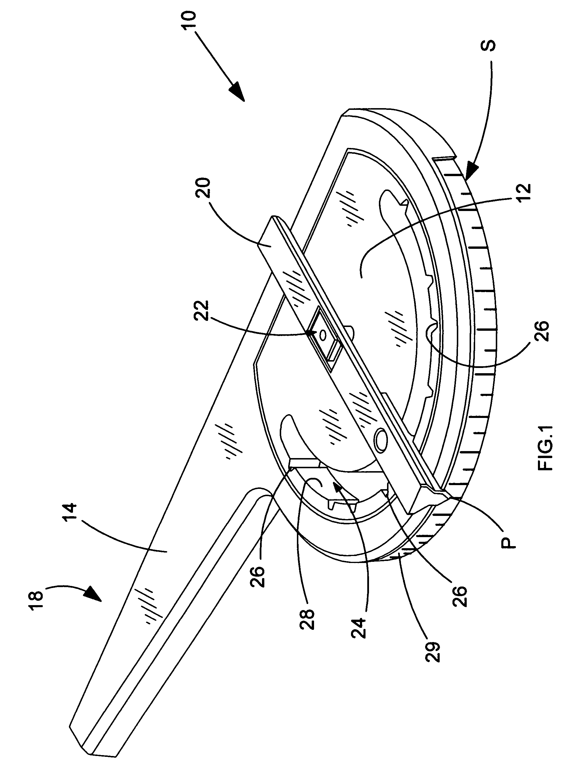
[0031]With this in mind, and with reference to FIG. 1, a detachable setsquare 10 embodying the present invention is now described. The setsquare 10 preferably comprises a body portion 12 having an arm 14 extending therefrom. The arm comprises...


PUM

PropertyMeasurementUnit
V-shapeaaaaaaaaaa
angular displacementsaaaaaaaaaa
angular displacementaaaaaaaaaa

Abstract

An adjustable setsquare for a power tool guide rail is described. The setsquare comprises an attachment member, in the form of a bar, for locating into a channel on the guide rail. The cross section of the attachment means is generally V-shaped and arranged such that the setsquare can be removed and reattached to the guide rail with consistency, whereby the angular displacement between a reference surface of the setsquare and the intended line of cut to be made by a power tool disposed on the guide rail remains constant after each reattachment of the setsquare.

Description

CROSS-REFERENCE TO RELATED APPLICATION[0001]This application claims priority to European Patent Application No. EP 06113869.9, filed May 12, 2006. The entire contents of that application are expressly incorporated herein by reference thereto.FIELD OF THE INVENTION[0002]The present invention relates to an attachment suitable for use on a guide rail. The guide rail is used to guide power tools, such as a circular saw or jigsaw, during, for example, cutting operations. The attachment can be used to set the angle of the guide rail on a work-piece with respect to a work-piece datum.BACKGROUND OF THE INVENTION[0003]The present invention is described below with reference to circular saws. However, this reference is not intended to limit the scope of the invention in any manner; the present invention can be used with any type of guide rail and any power tool used therewith.[0004]Hand operated electrically powered cutting tools are typically used to cut a work-piece, such as wood panels or t...

Claims


Application Information

Patent Timeline
Patent Type & Authority Patents(United States)
IPC IPC(8): B23Q17/22B26D7/06
CPCB23Q9/0085Y10T83/875
Inventor SARGEANT, PAUL
Owner BLACK & DECKER INC
Learn More