
System and method for depth determination of cracks in conducting structures

a conducting structure and depth determination technology, applied in the field of non-destructive testing, can solve the problems of limited penetration depth into the material, inability to detect the probe, and poor readings

Inactive Publication Date: 2009-04-14
TECHNION RES & DEV FOUND LTD
View PDF11 Cites 11 Cited by
  • Summary
  • Abstract
  • Description
  • Claims
  • Application Information

AI Technical Summary

Benefits of technology

The present invention provides a system and method for detecting and determining the depth of cracks in conducting structures, such as surface penetrating cracks and back cracks. The invention uses alternating current and measures the voltage drop to estimate the depth of the crack. The method involves applying alternating current to a sample, measuring voltage drop between two probes separated by a gap of distant Δ, and making electrical contact with the sample. The method can be used for both surface penetrating cracks and back cracks. The invention provides a more accurate and reliable method for estimating the depth of cracks in conducting structures, which can help to improve the detection and prevention of damage to power transmission systems.

Problems solved by technology

This method has several limitations, among them: the surface of the material must be accessible, the finish of the material may cause bad readings, the depth of penetration into the material is limited, and flaws that lie parallel to the probe may be undetectable.Ultrasonic Inspection (Pulse-Echo)—this method uses High frequency sound waves introduced into a material and reflected back from surfaces or flaws.
However, there is no general solution that bridges these two modes in a seamless fashion.
Moreover, techniques used in the art do not allow detection locating and characterization of flaws below the surface, or on the surface other than the inspected surface.

Method used


Image

  • System and method for depth determination of cracks in conducting structures
  • System and method for depth determination of cracks in conducting structures
  • System and method for depth determination of cracks in conducting structures

Examples


Embodiment Construction

[0079]Before explaining at least one embodiment of the invention in detail, it is to be understood that the invention is not limited in its application to the details of construction and the arrangement of the components set forth in the following description or illustrated in the drawings. The invention is capable of other embodiments or of being practiced or carried out in various ways. Also, it is to be understood that the phraseology and terminology employed herein is for the purpose of description and should not be regarded as limiting.

[0080]The drawings are generally not to scale. For clarity, non-essential elements were omitted from some of the drawings. In discussion of the various figures described herein below, like numbers refer to like parts.

[0081]As used herein, an element or step recited in the singular and proceeded with the word “a” or “an” should be understood as not excluding plural elements or steps, unless such exclusion is explicitly recited.

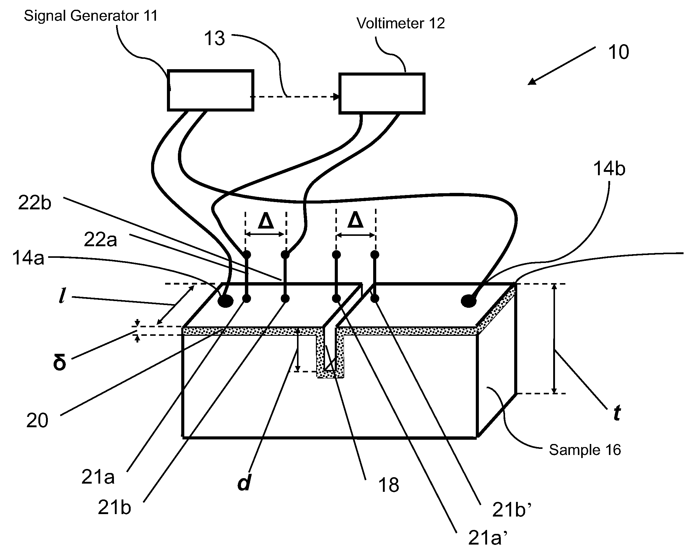
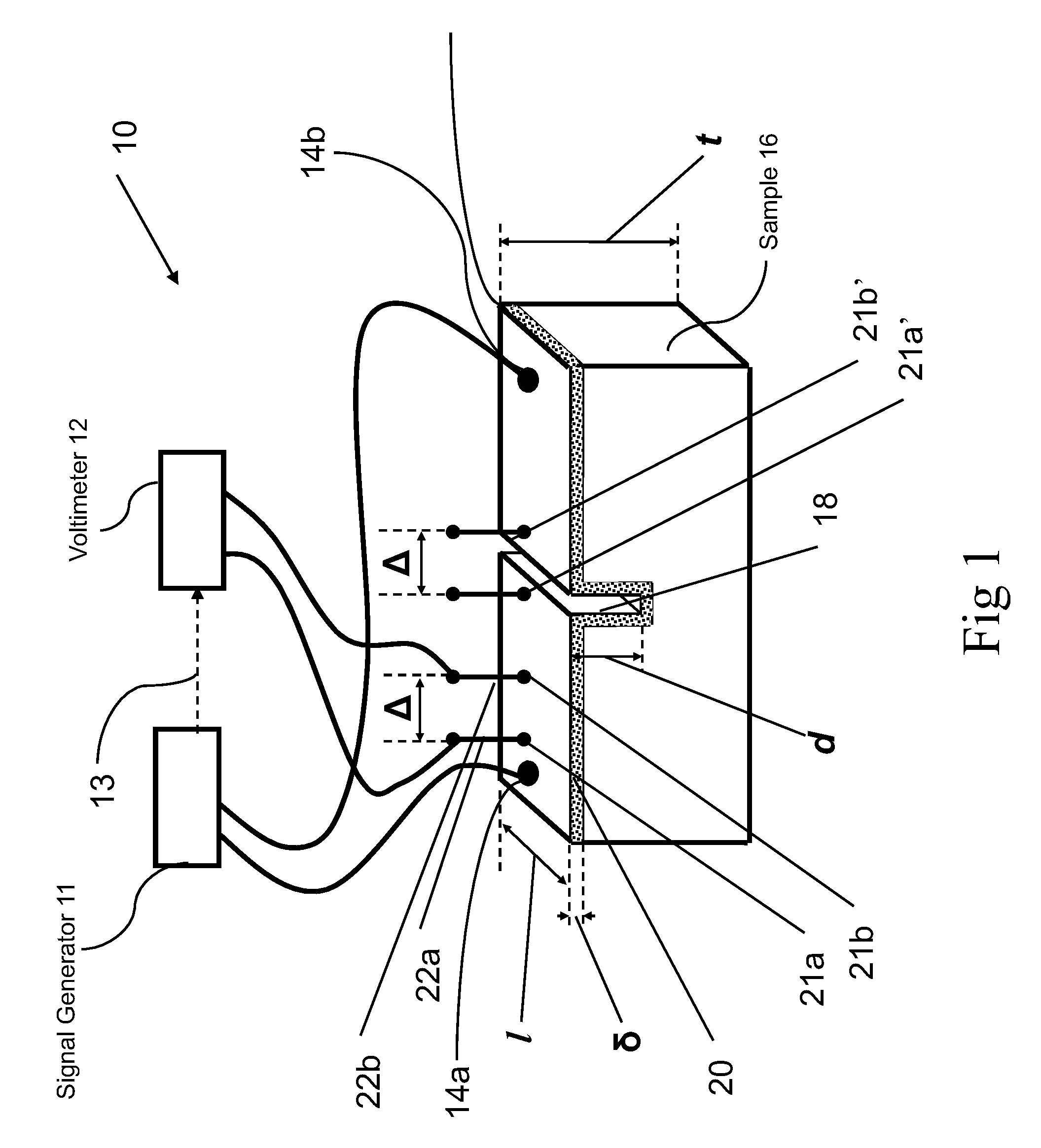
[0082]FIG. 1 schemat...


PUM


Abstract

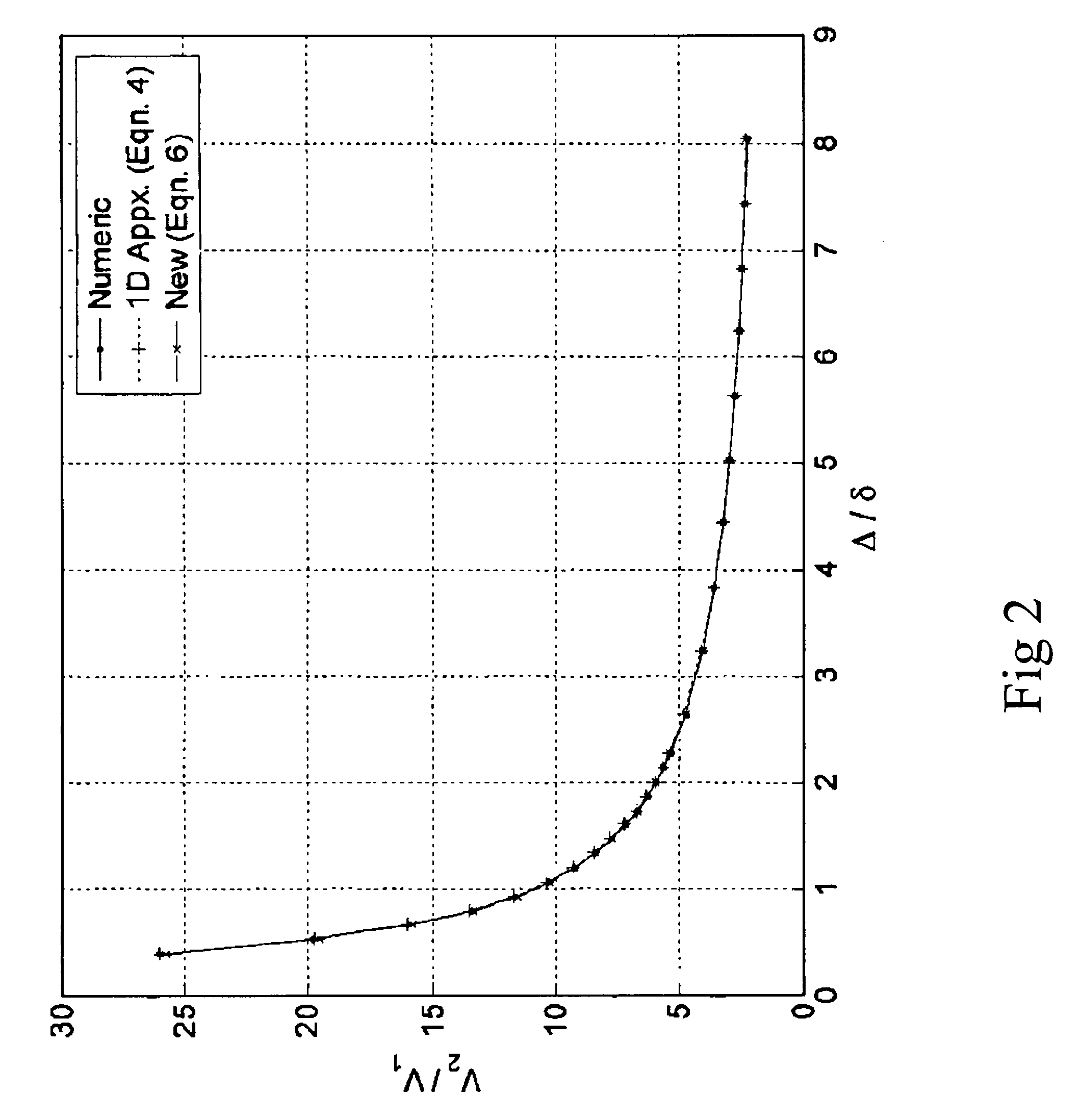
The alternating current potential drop ACPD technique is used to monitor surface cracks in electrical conductors. At high frequencies, the current flows in a superficial skin layer. Two distinct solutions are currently available for the thin and thick skin cases. However, there is no general solution that bridges these two modes in a seamless fashion. A numerical model is used to analyze the ACPD of a surface crack with uniform depth. A general solution is given that bridges the thin and thick skin solutions, which closely matches the numerical results, irrespective of the skin thickness. Methods for estimating depth of cracks are provided for surface penetrating cracks and back cracks.

Description

[0001]This present application claims the benefit of earlier U.S. provisional patent application Ser. No. 60 / 778,845 filed on Mar. 6, 2006 by Hagit et al. and entitled: “Electrocal tomography of hidden flowsnin conductors using the alternating current potential drop”.FIELD OF THE INVENTION[0002]The present invention is related generally to the field of nondestructive testing and specifically to alternating current potential drop (ACPD) technique for detecting cracks in conducting samples.BACKGROUND OF THE INVENTION[0003]Nondestructive testing (NDT) is the examination of an object or material in any manner that will not impair its future usefulness. NDT is performed to evaluate the internal and / or external condition of materials, components and structures without any damage to them.[0004]In the industry NDT technologies are used to help ensure the integrity and reliability of products being provided to the end users. The NDT process may range anywhere from a simple visual inspection ...

Claims


Application Information

Patent Timeline
Patent Type & Authority Patents(United States)
IPC IPC(8): G01R19/00
CPCG01N27/20
Inventor SAGUY, HAGITRITTEL, DANIEL
Owner TECHNION RES & DEV FOUND LTD
Learn More