
Emergency mode operation in a wireless communication network

a wireless communication network and emergency mode technology, applied in the field of telecommunications, can solve the problems of inability to adequately transmit signals between base station transceivers and mobile stations within rubble, network less than optimal for addressing such situations, and traditional wireless communication networks prevent or degrade any use of wireless communication devices. to achieve the effect of enhancing location capacity

Inactive Publication Date: 2009-04-14
LUCENT TECH INC
View PDF18 Cites 67 Cited by
  • Summary
  • Abstract
  • Description
  • Claims
  • Application Information

AI Technical Summary

Benefits of technology

"The patent describes a method for switching between a normal operating mode and an emergency mode for a wireless network. The emergency mode can be activated when there are certain circumstances, such as using a dedicated emergency channel or using portable devices to communicate. The mobile stations can also switch into emergency mode on their own. The technical effect of this invention is to provide a means for ensuring reliable communication in times of crisis or emergency situations."

Problems solved by technology

There are occasions where a wireless communication network would be useful but the normal communication techniques render the network less than optimal for addressing such situations.
The limitations on traditional wireless communication networks prevent or degrade any use of wireless communication devices for such situations.
For example, the debris associated with the collapse of the World Trade Center made it impossible for adequate signal transmission between base station transceivers and mobile stations within the rubble.
Additionally, much of the network infrastructure in the vicinity of the World Trade Center was damaged and, therefore, not effective.
Further, the additional load on the system from the large number of individuals attempting to contact others using wireless communications taxed system resources, which made them less available for targeted search and rescue efforts.

Method used


Image

  • Emergency mode operation in a wireless communication network
  • Emergency mode operation in a wireless communication network
  • Emergency mode operation in a wireless communication network

Examples


Embodiment Construction

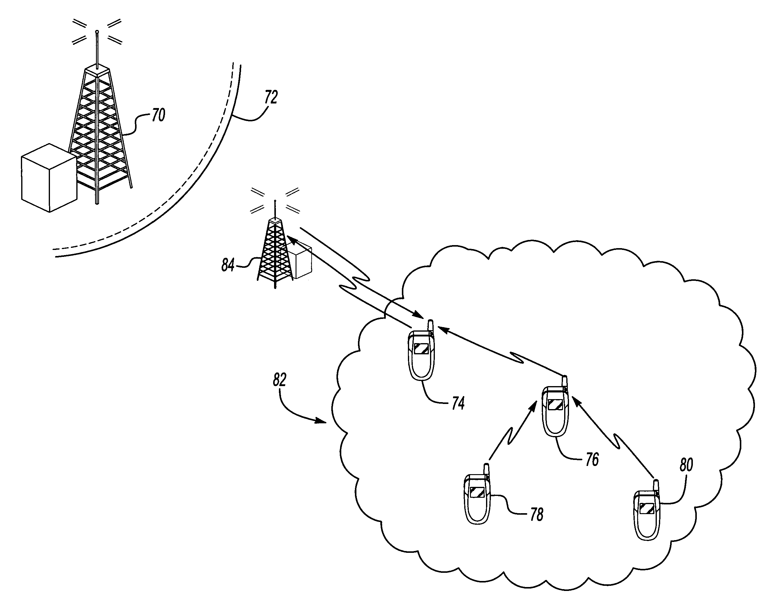
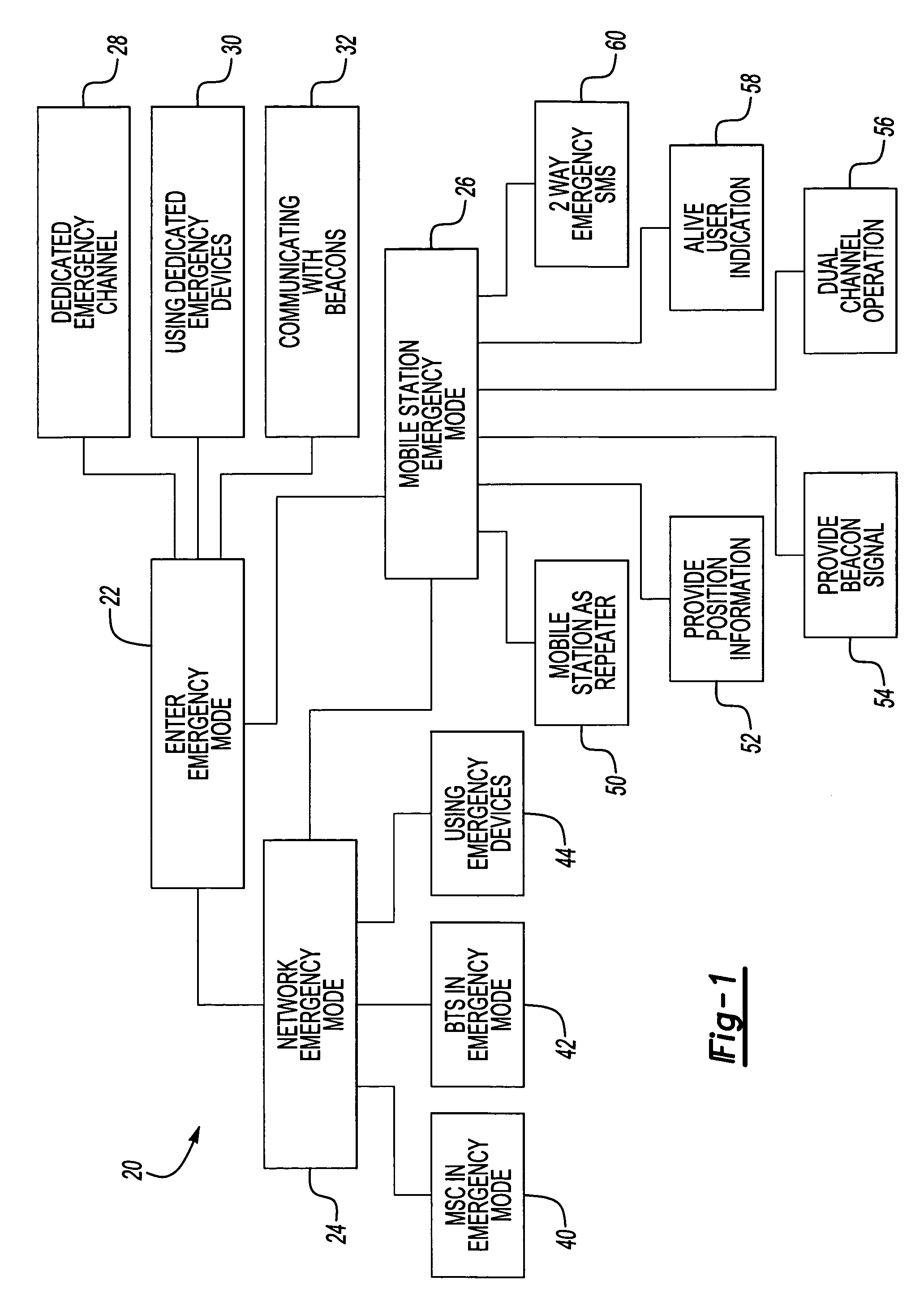
[0018]FIG. 1 schematically shows a wireless communication network 20 that is capable of operating in a normal operating mode for most situations and in an emergency operating mode under selected circumstances. When disaster or emergency conditions occur, at least portions of the network 20 enter into an emergency mode at 22. Entering the emergency mode may occur at a network level at 24 or at a mobile station level at 26.

[0019]Controlling when to enter the emergency mode occurs in one example based upon manual user input to an appropriate network device or a mobile station. In another example, the wireless communication device or devices that enter the emergency mode are capable of automatically entering the emergency mode. Given this description, those skilled in the art will be able to develop an appropriate manner for entering an emergency operating mode to meet the needs of their particular situation and to accommodate the particular technologies of the wireless network with whi...


PUM


Abstract

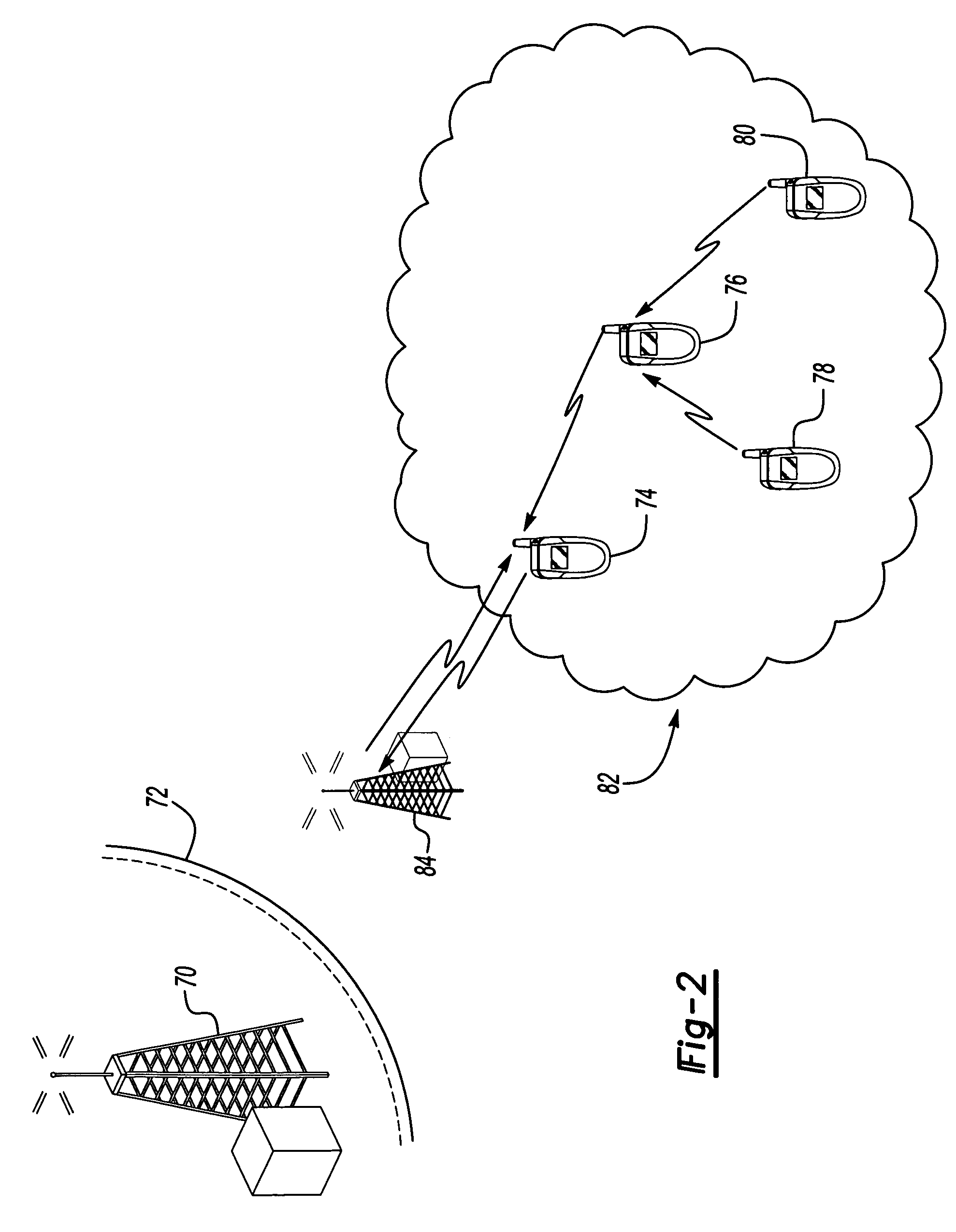
A wireless communication network 20 operates in an emergency mode 22. In one example, network components enter an emergency mode 24. In another example, mobile stations enter an emergency mode 26. Various disclosed emergency mode features such as having a dedicated emergency channel, using dedicated emergency devices, using mobile stations as repeaters, providing alive user indications and utilizing beacon signals can be combined in different ways to facilitate search and rescue operations, for example.

Description

CROSS REFERENCE TO RELATED APPLICATIONS[0001]This application claims priority to U.S. Provisional Application No. 60 / 586,507 which was filed on Jul. 9, 2004.FIELD OF THE INVENTION[0002]This invention generally relates to telecommunications. More particularly, this invention relates to wireless communication systems.DESCRIPTION OF THE RELATED ART[0003]Wireless communication systems are well known. Geographic regions are divided into cells or sectors that are served by base station transceivers. Mobile stations, such as cellular phones, communicate with a base station when the mobile station is within the corresponding cell, for example. As the mobile station moves between cells, the various base stations communicate signals to and from the mobile stations.[0004]Mobile switching centers operate in a known manner for allowing the mobile station communications to be received by another mobile station or a line-based telephone, for example.[0005]In addition to voice communications, a var...

Claims


Application Information

Patent Timeline
Patent Type & Authority Patents(United States)
IPC IPC(8): H04B7/15
CPCH04W4/22H04W76/007H04W88/18H04W76/50H04W4/90
Inventor MALONE, III, BERNARD L.
Owner LUCENT TECH INC
Learn More