
Air conditioner

a technology for air conditioners and fans, applied in the field of air conditioners, can solve the problems of deteriorating blowing performance, reverse inhalation from the outlet toward the outlet, deteriorating blowing efficiency, etc., and achieve the effects of reducing noise, preventing deterioration in blowing performance, and preventing the generation of reverse inhalation

Active Publication Date: 2009-04-14
MITSUBISHI ELECTRIC CORP
View PDF10 Cites 9 Cited by
  • Summary
  • Abstract
  • Description
  • Claims
  • Application Information

AI Technical Summary

Benefits of technology

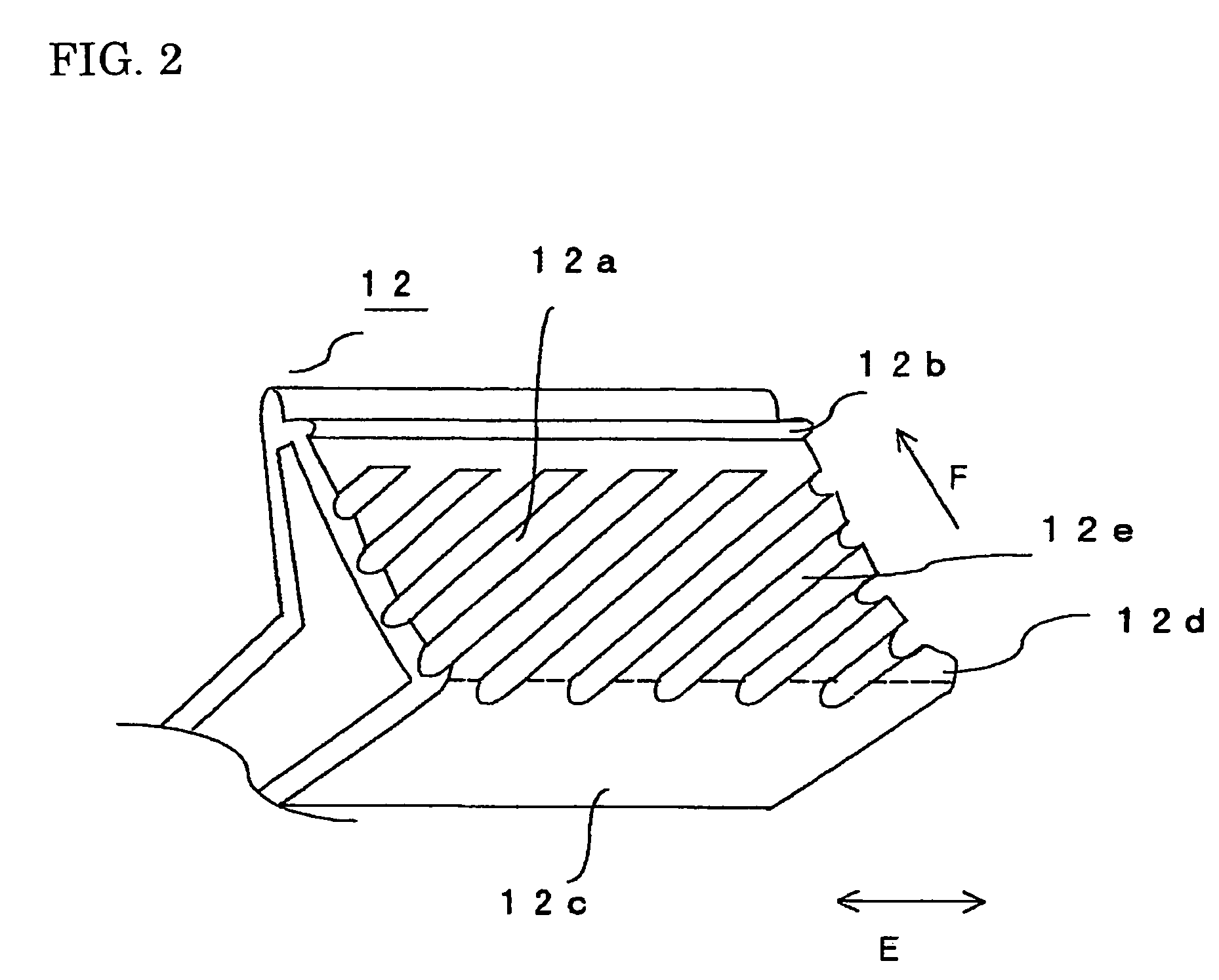
[0018]In the air conditioner according to the present invention, turbulences are generated in an air stream flowing along a surface of the stabilizer opposing the impeller by arranging the concave-convex portions on the opposing surface, so that the cross-flow eddy is stabilized to prevent deterioration in blowing performance and the reverse inhalation generation. Furthermore, the positions of the concave-convex portions are arranged apart in the rotational axis direction of the impeller, so that the air conditioner capable of reducing noise can be obtained.
[0018]In the air conditioner according to the present invention, turbulences are generated in an air stream flowing along a surface of the stabilizer opposing the impeller by arranging the concave-convex portions on the opposing surface, so that the cross-flow eddy is stabilized to prevent deterioration in blowing performance and the reverse inhalation generation. Furthermore, the positions of the concave-convex portions are arranged apart in the rotational axis direction of the impeller, so that the air conditioner capable of reducing noise can be obtained.

Problems solved by technology

Conversely, the broader the gap, the broad band noise is more reduced; but the air flowing through the gap becomes unstable, deteriorating the blowing efficiency and generating the back flow from the outlet toward the inlet due to the air flow separation from the wall of the casing or the stabilizer.
In particular, when the flow stability is to be maintained by reducing the gap between the impeller and the rear guider to some extent, the concave portion comes close to the impeller, so that the draft resistance is increased by the concave portion arranged in a direction substantially perpendicular to the fluid flowing direction, deteriorating the blowing performance.
Since the shortest distance between the impeller and the stabilizer becomes uniform in the direction of the rotational axis due to the inclination of the projection, the cross-flow eddy currents produced in the impeller cannot be stabilized, so that a problem of the reverse inhalation from the outlet toward the inlet arises.
There is also a problem that the projection extending in the direction of the rotational axis increases the noise.

Method used


Image

  • Air conditioner
  • Air conditioner
  • Air conditioner

Examples


first embodiment

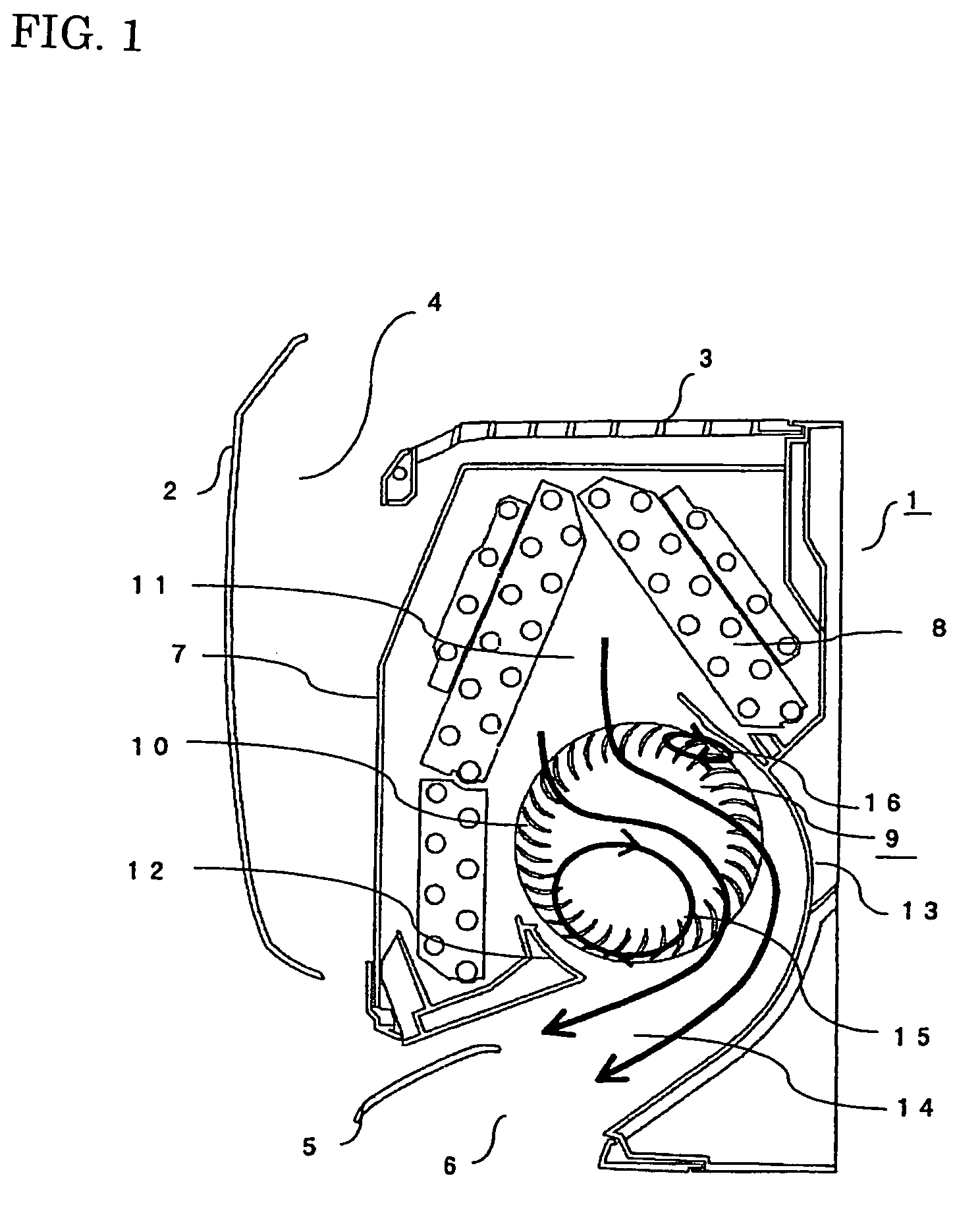
[0040]FIG. 1 is a sectional view of an indoor unit of an air conditioner according to a first embodiment of the present invention. In the drawing, the indoor unit 1 of the air conditioner is installed in a room, and an air inlet 4 covered with a front panel 2 and a top grill 3 is provided at the upper front of the indoor unit 1 so as to oppose the room inside. Also, an air outlet 6 having an opening restricted in direction and area with a wind-direction adjusting vane 5 is provided at the lower front of the unit. Sequentially, an air flow-path extending from the air inlet 4 to the air outlet 6 is formed. In the midstream of the air flow-path, a pre-filter 7 for eliminating foreign materials contained in the flowing room air, a heat exchanger 8 for exchanging heat between refrigerant flowing through piping and the flowing room air, and a cross-flow fan 9 are arranged. The cross-flow fan 9 is composed of a cylindrical fan body extending in the direction of the rotational axis, includi...

second embodiment

[0082]An indoor unit of an air conditioner according to a second embodiment of the present invention will be described. The sectional structure of the indoor unit according to the embodiment is the same as that shown in FIG. 1, and the air conditioning operation by changing air quality in a room is also the same as that according to the first embodiment, so that the descriptions are omitted.

[0083]When considering the gap between the impeller 10 and the casing 13, the narrower the gap, the air flowing through the gap is more stabilized, improving the blowing efficiency. However, broad band noise due to the collision of the high-speed air blowing off out of the impeller 10 with the casing 13 is increased. Conversely, the broader the gap between the impeller 10 and the casing 13, the broad band noise is more reduced. However, the air flowing through the gap becomes unstable, deteriorating the blowing efficiency and generating the back flow from the outlet toward the impeller 10. That i...

third embodiment

[0114]An indoor unit of an air conditioner according to a third embodiment of the present invention will be described. The sectional structure of the indoor unit according to the embodiment is the same as that shown in FIG. 1, and the air conditioning operation by changing air quality in a room is also the same as that according to the first embodiment, so that the descriptions are omitted.

[0115]FIG. 16 is a perspective view of the cross-flow fan 9 according to the embodiment, in which like reference characters designate like components equivalent or common to FIGS. 2 and 11. FIG. 17(a) is a front view of the stabilizer 12 viewed from the surface 12a opposing the impeller 10, and FIG. 17(b) is a front view of the casing 13 viewed from the surface 13a opposing the impeller 10. The stabilizer 12 according to the embodiment, as shown in FIG. 17(a), has a plurality of grooves 12e. The detailed structure and operation / working effect with regard to the concave-convex portions of the stabi...


PUM


Abstract

In an air conditioner, reverse inhalation is prevented while broad band noise and wind sound are reduced. A projection arranged at the leading end of a stabilizer on the downstream side of an air stream flowing along a surface of the stabilizer opposing an impeller and protrudes toward the impeller to define the shortest distance to the impeller. A plurality of grooves or projections are provided on the opposing surface on the upstream side of the projection to disturb the air stream flowing along the opposing surface. The positions of the grooves or the projections are arranged apart in a rotational axis direction. A plurality of convex portions are provided to disturb an air stream flowing along a surface of a casing opposing the impellers. The positions of the convex portions are arranged apart in the rotational axis direction of the impeller.

Description

TECHNICAL FIELD[0001]The present invention relates to air conditioners, and more specifically, it relates to an indoor unit having a cross-flow fan.BACKGROUND ART[0002]A cross-flow fan for use in conventional air conditioners includes a cross-flow impeller having a plurality of fan bodies linked together, and a rear guider and a stabilizer, which are arranged across the impeller for guiding fluid from an inlet toward an outlet. The rear guider is arranged to have an area covering the side peripheral surface of the impeller larger than that of the stabilizer, and the stabilizer is arranged at a position nearer to the side peripheral surface of the impeller than the rear guider. The rear guider is provided with concave portions formed continuously in a direction perpendicular to the fluid flowing direction, thereby reducing an interference sound produced at a gap between the impeller and the rear guider (see Patent Document 1, for example). The concave portions are formed slightly obl...

Claims


Application Information

Patent Timeline
Patent Type & Authority Patents(United States)
IPC IPC(8): F04D5/00F04D17/04F04D29/42F04D29/66F24F1/0057
CPCF04D17/04F04D29/422F24F1/0007F24F13/24F24F1/0025F24F2001/0048F24F1/0057
Inventor HIRAKAWA, SEIJIYAMADA, SHOJITAKAMORI, AKIRASHIROTA, MITSUHIROYOSHIKAWA, TOSHIAKIIKEDA, TAKASHIOKAZAWA, HIROKI
Owner MITSUBISHI ELECTRIC CORP
Learn More