Determination of time-difference of arrival and angle of arrival
a time-difference of arrival and angle technology, applied in the field of time-difference of arrival and angle, can solve the problems of limited practical use of conventional crosscorrelation techniques based, explicitly or implicitly, on the assumptions of signal stationarity and noise gaussianity, and the disclosed crosslation is not well suited to time-difference of arrival (tdoa) determination. , to achieve the effect of mitigating the effect of noise in each signal
- Summary
- Abstract
- Description
- Claims
- Application Information
AI Technical Summary
Benefits of technology
Problems solved by technology
Method used
Image
Examples
first preferred embodiment
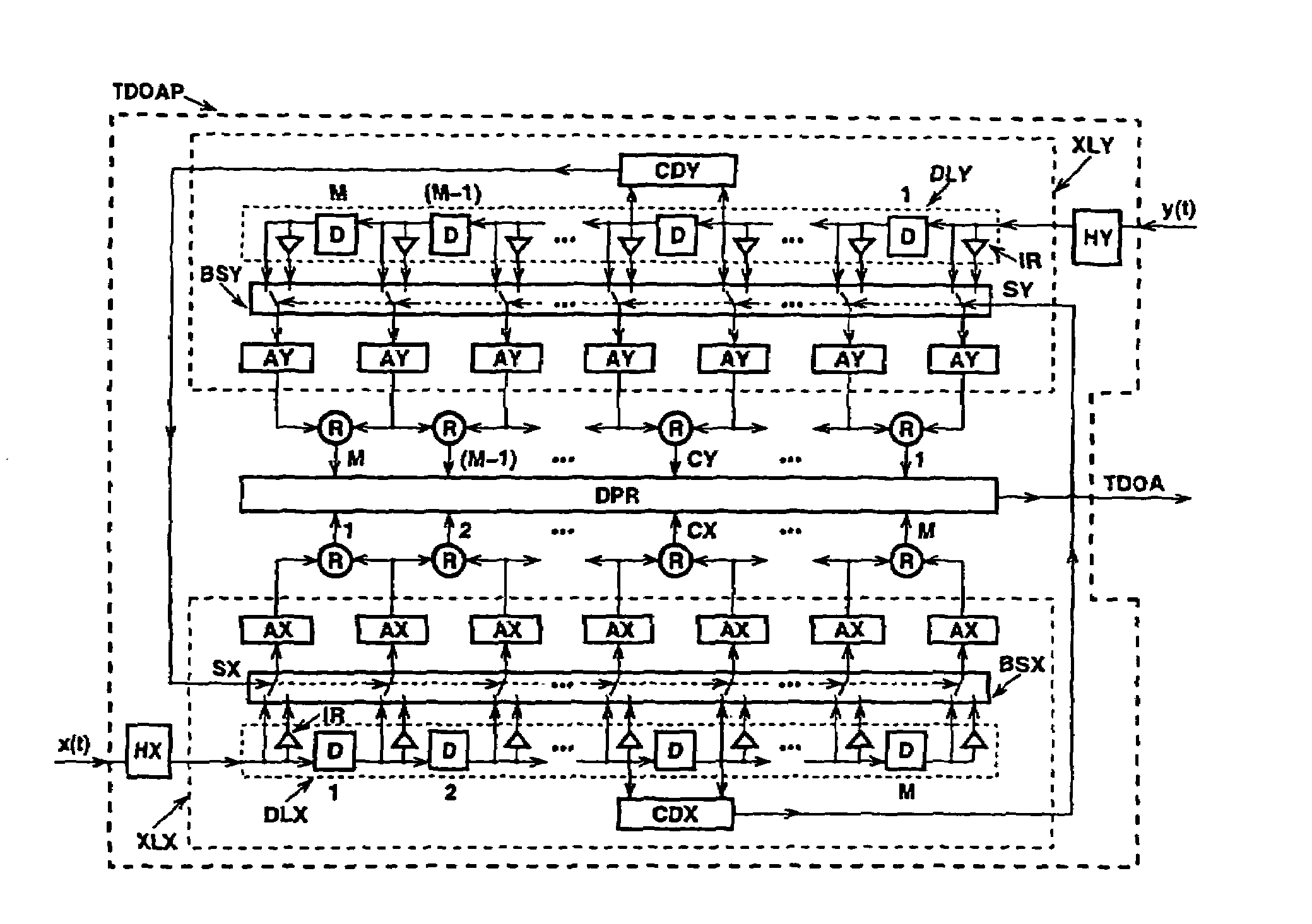
[0050]FIG. 6 is a block diagram of a time-difference of arrival (TDOA) processor (TDOAP) arranged to operate in accordance with the invention and suitable for use in the network of FIG. 4. The processor comprises two hard limiters, HX and HY, two interconnected crosslators, XLX and XLY, two arrays of identical difference circuits, R, and a data processor DPR.
[0051]The crosslator XLX comprises a cascade DLX of M unit-delay cells D, a bank of switches BSX, (M+1) identical averaging (or integrating) circuits AX and a zero-crossing detector CDX. Each delay cell D can supply both a signal and its polarity-reversed replica.
[0052]Similarly, the crosslator XLY comprises a cascade DLY of M unit-delay cells D, a bank of switches BSY, (M+1) identical averaging (or integrating) circuits AY and a zero-crossing detector CDY. Each delay cell D can supply both a signal and its polarity-reversed replica.
[0053]Two input signals, x(t) and y(t), to be processed jointly by the time-difference of arrival...
example
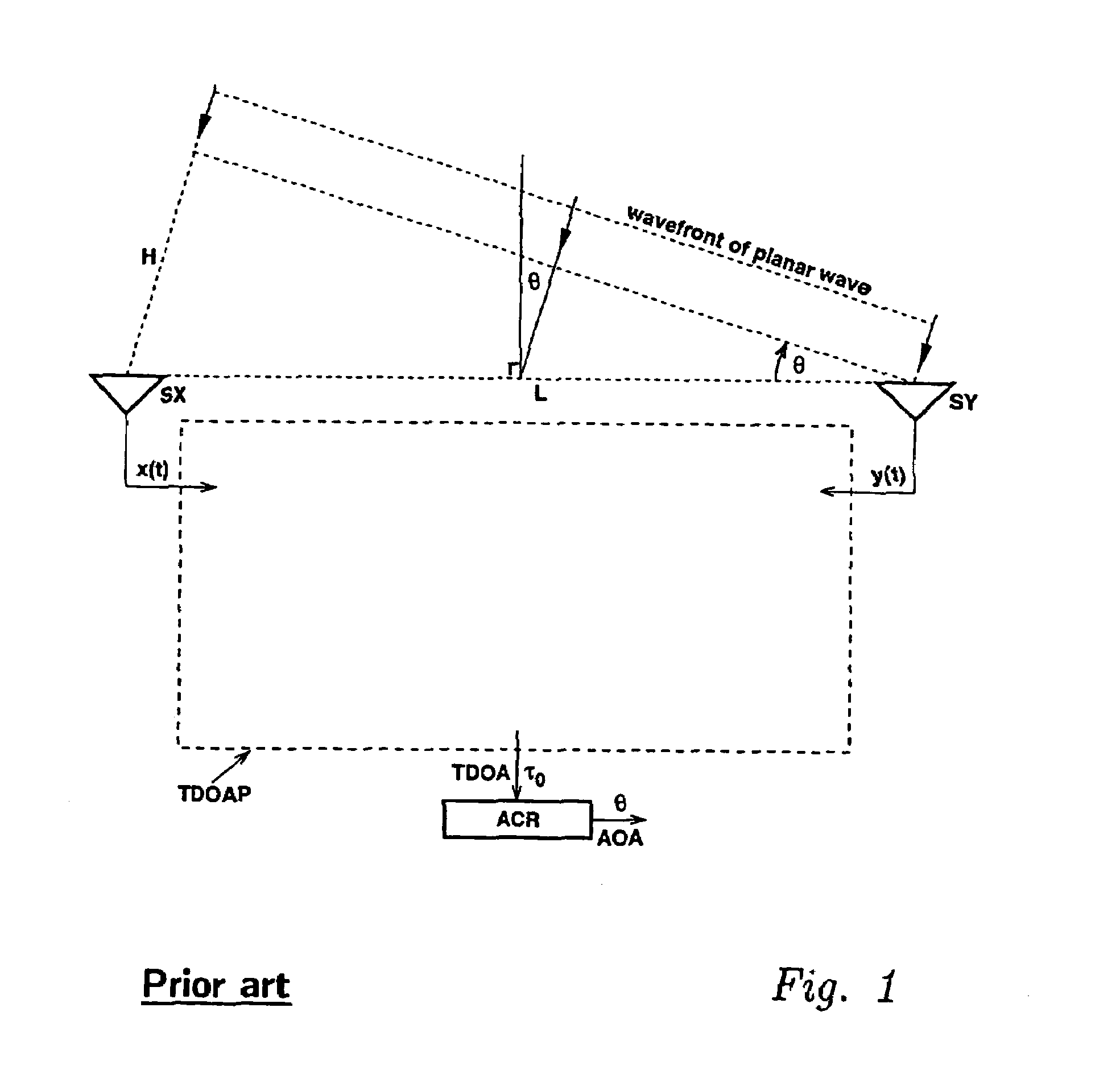
[0069]Consider the sensor geometry depicted in FIG. 1 and assume that the distance L between sensors SX and SY is equal to 5 cm, and the angular field of view (FOV) of each sensor is limited by −60°
[0070]τmax=Lsin60∘vs≈127.4µs[0071] where vs=340 m / s is the speed of sound; the required time resolution Δτ is
[0072]Δτ=Lsin1∘vs≈2.6µs[0073] Therefore, for the design purposes, it can be assumed that Δτ=2.5 μs. Consequently, each delay line will consist of 103 delay cells, each introducing a delay of 2.5 μs, which results in a total delay of 257.5 μs.[0074]When cell number 52 is selected to be the centre cell, the range of available delays will be ±127.5 μs. For optimum system operation, the rise time and the fall time of binary waveforms produced by hard limiters should be less than 2.5 μs.
[0075]The disclosed time-difference of arrival (TDOA) processor:[0076]utilizes concurrently trigger pulses obtained from one of the signals x(t) and y(t) to synchronize the analysis of th...
second preferred embodiment
[0080]The difference between two delayed replicas of a crosslation function can be obtained through the use of an auxiliary circuit following each of the two zero-crossing detectors, and without the use of any explicit difference circuits.
[0081]FIG. 9 is a block diagram of a modified time-difference of arrival (TDOA) processor (TDOAP) arranged to operate in accordance with the invention and also suitable for use with the network of FIG. 4. The processor comprises two hard limiters, HX and HY, two crosscoupled modified crosslators, DXX and DXY, and a data processor DPR. Each of the zero-crossing detectors, CDX and CDY, is followed by an auxiliary delay unit U and a summer S.
[0082]When a rising edge (a zero upcrossing) is detected, the positive pulse is produced at the zero-crossing detector's output. Because this pulse is delayed and inverted by the auxiliary delay unit U, the summer S will produce a pulse doublet comprising a primary positive pulse followed shortly by its negative r...
PUM
 Abstract
Description
Claims
Application Information
 - R&D
- Intellectual Property
- Life Sciences
- Materials
- Tech Scout
- Unparalleled Data Quality
- Higher Quality Content
- 60% Fewer Hallucinations
Browse by: Latest US Patents, China's latest patents, Technical Efficacy Thesaurus, Application Domain, Technology Topic, Popular Technical Reports.
© 2025 PatSnap. All rights reserved.Legal|Privacy policy|Modern Slavery Act Transparency Statement|Sitemap|About US| Contact US: help@patsnap.com


