
Continuous infrared furnace

Active Publication Date: 2009-04-07
ILLINOIS TOOL WORKS INC
View PDF25 Cites 34 Cited by
  • Summary
  • Abstract
  • Description
  • Claims
  • Application Information

AI Technical Summary

Benefits of technology

The invention is a furnace that uses infrared lamps to heat materials to be treated through a heat transfer zone. The furnace has an upper and lower portion and a conveyor that moves the material through the heat transfer zone. The conveyor supports are oriented parallel or skew to the direction of travel to ensure consistent radiation from the lamps across the material. The furnace also has a cooling zone for cooling the material using a radiant cooler that uses water at a pressure of 60 psig or higher. The technical effects of the invention include improved heating and cooling of materials, consistent radiation across the material, and improved efficiency of the heat transfer process.

Problems solved by technology

The high volume fabrication and treatment of heat processed or heat annealed devices entails many opportunities and challenges.

Method used


Image

  • Continuous infrared furnace
  • Continuous infrared furnace
  • Continuous infrared furnace

Examples


Embodiment Construction

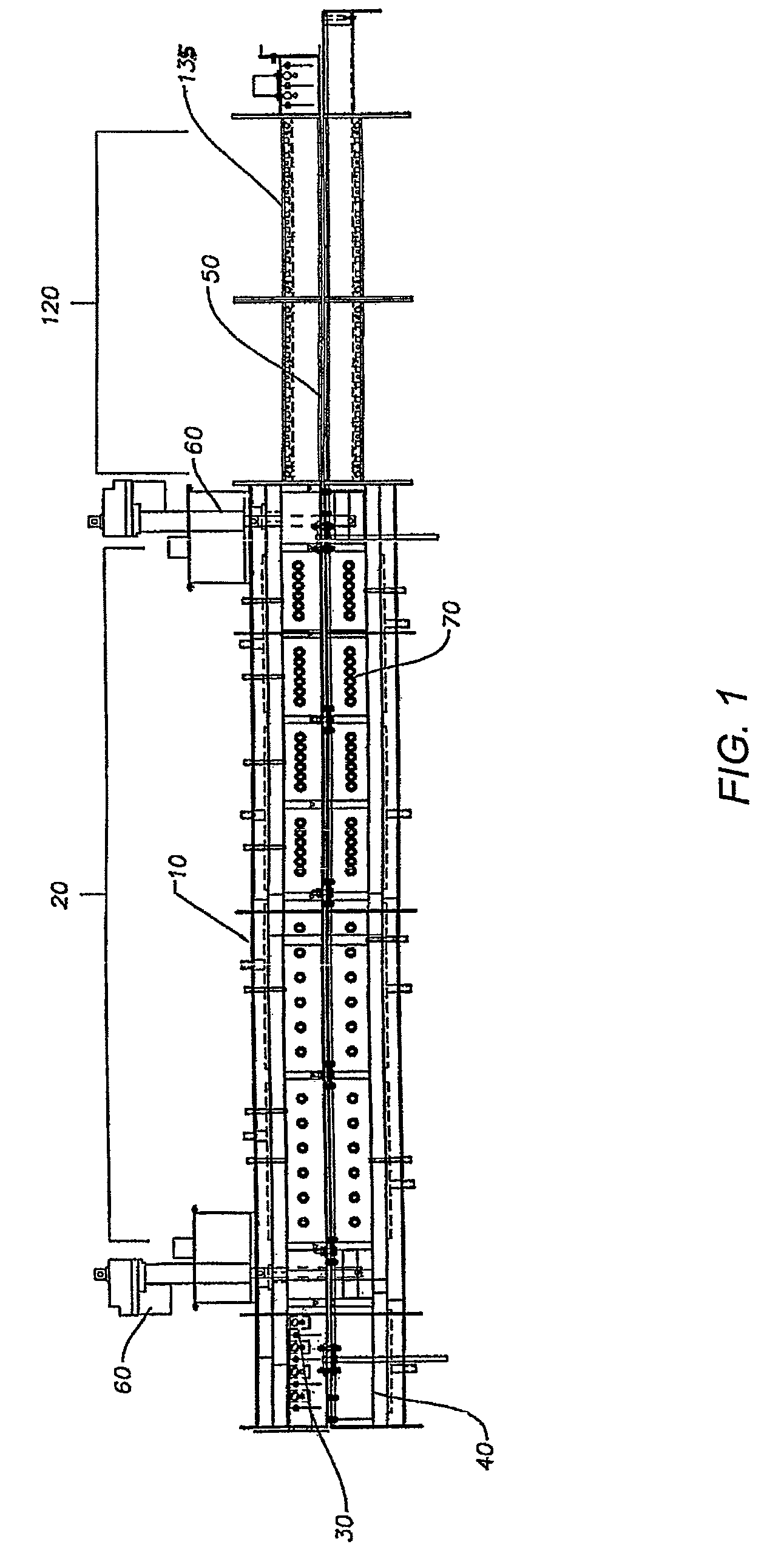
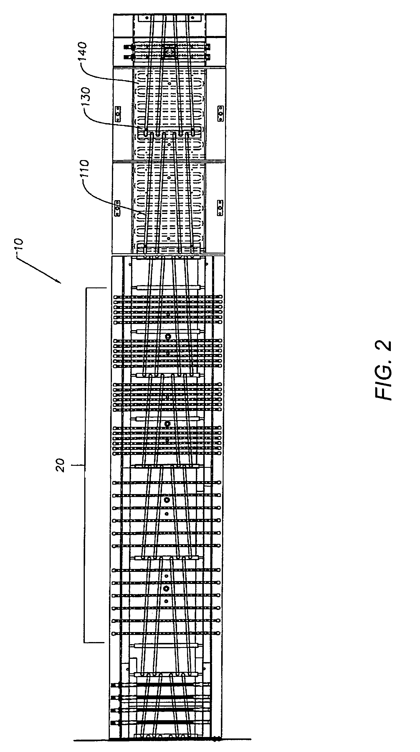
[0017]Turning now to the figures, FIG. 1 is a side view of an embodiment of a furnace in accordance with the invention. The furnace 10 has a heat transfer zone generally indicated at 20 for heating a material to be treated (not shown). The heat transfer zone 20 has an upper portion 30 and a lower portion 40. A conveyor 50 transports material to be treated through heat transfer zone 20 along a direction of travel. The conveyor 50 may be, for example, a conveyor belt, a walking beam, or other conveyor known in the art. A jack 60 allows movement of the lower portion 40 of the heat transfer zone 20 to allow access to the interior of the heat transfer zone 20 and to components therein. A jack 60, as used in this application, means a device for raising and lowering objects by means of force applied with a lever, screw, hydraulic press, or other means known in the art. The heat transfer zone 20 may also include one or more infrared lamps 70. These infrared lamps may be, for example, quartz...


PUM

PropertyMeasurementUnit
pressureaaaaaaaaaa
pressureaaaaaaaaaa
heataaaaaaaaaa

Abstract

A furnace of controlled heating and treatment of material using infrared radiation. The furnace is capable of continuous infrared treating of material with consistent radiation being applied to the material, ease of access to the furnace for maintenance cleaning and repair, excellent control of radiant cooling of the material to be treated, and ease of maintenance of a volatile component condenser.

Description

FIELD OF THE INVENTION[0001]The invention is directed to a continuous infrared furnace for heating and treating work pieces, and to techniques for improving performance, reliability, and maintainability of the same.BACKGROUND OF THE INVENTION[0002]Continuous infrared furnaces and ovens are widely used for in a variety of industries. Materials that may be treated in a continuous infrared furnace may include painted or coated materials that require specific curing conditions, components that require heat melt solder (i.e. ball grid arrays), pre-heating metals, circuit boards, silicon wafers treated through zone-melt processes, materials for use in photovoltaic cells requiring conductive paste to be fused thereto, and any other material that one can conceive of that is can benefit from controlled infrared radiation.[0003]An infrared furnace provided with the ability to convey material through the furnace may be highly useful because heating and cooling zones provided throughout the fur...

Claims


Application Information

Patent Timeline
Patent Type & Authority Patents(United States)
IPC IPC(8): F27B9/06F27B9/00
CPCF27B9/02F27B9/066F27B9/202F27B9/24F27B9/30F27D9/00
Inventor MELGAARD, HANS L.WEIERKE, MATT
Owner ILLINOIS TOOL WORKS INC
Learn More