
Hydraulic tensioner

a technology of hydraulic tensioner and tensioner body, which is applied in the direction of mechanical equipment, belts/chains/gearings, etc., can solve the problems of reducing the space available in the high pressure chamber r, affecting the response characteristics of the tensioner, and the limitation of the amount of oil in the chamber r, so as to improve the response characteristics, reduce the diameter, and increase the volume of the high pressure chamber

Active Publication Date: 2009-04-07
TSUBAKIMOTO CHAIN CO
View PDF21 Cites 3 Cited by
  • Summary
  • Abstract
  • Description
  • Claims
  • Application Information

AI Technical Summary

Benefits of technology

[0011]Because the check valve is recessed in a check valve unit-accommodating hole formed at the rear end of the plunger-accommodating hole, the volume of high pressure chamber can be made larger so that the tensioner has improved response characteristics. Since the rear end of the plunger-biasing spring is seated on a flat surface of the check valve unit, it need not surround the check valve unit, and therefore the spring can have a smaller diameter than that of the conventional plunger-biasing spring. The size of the plunger can also be reduced, and a more compact and less heavy tensioner can be realized. Additionally, the reduction of the diameter of the plunger-biasing spring avoids bending and buckling of the spring and resulting contact resistance. Therefore, smooth retracting and extending movement of the plunger can be realized.
[0012]Since the diameter of the check valve unit-accommodating hole is smaller than the diameter of the plunger-accommodating hole, and the rear end of the plunger-biasing spring fits into the check valve unit-accommodating hole, when an impact is imparted to the tip of the plunger, the position of the plunger-biasing spring can be reliably maintained. An annular space, forward of the step formed where the check valve unit-accommodating hole meets the plunger-accommodating hole, receives the outer wall of the plunger as the plunger extends and retracts. The plunger-biasing spring is located inward relative this annular space, and its radial expansion is restricted by the wall of the hole check valve unit-accommodating hole. Consequently, interference between the plunger and the plunger-biasing spring is avoided, and smooth and reliable extension and retraction of the plunger can be realized.
[0013]Since the check valve unit comprises a cylindrical ball seat communicating with an oil supply passage, a check ball, which blocks reverse flow of oil by contacting the ball seat, a ball-biasing spring, which biases the check ball toward the ball seat, and a retainer, which positions and supports the ball-biasing spring and limits movement of the check ball, the check valve unit is a simplified integral structure, and can be produced without special machining. Furthermore assembly of the check valve unit and incorporation of the unit into the tensioner can be carried out easily and with accuracy. As a result, the production cost of the tensioner can be significantly reduced.

Problems solved by technology

Therefore, the conventional retainer causes design problems, and prevents decreasing the diameter and reducing the weight of the plunger-biasing spring 530.
Furthermore, the available space in the high pressure chamber R is reduced because most of the check valve extends into the high pressure chamber R. Thus, the amount of oil which can be stored in the high pressure chamber R is limited by the presence of the check valve, and the limitation on the amount of oil in the chamber R adversely affects the tensioner's response characteristics.
Unless the retainer and ball seat fit properly in the housing, leakage of oil can occur, which results in troublesome problems.

Method used


Image

  • Hydraulic tensioner
  • Hydraulic tensioner
  • Hydraulic tensioner

Examples


Embodiment Construction

[0019]Briefly, the hydraulic tensioner according to the invention, as in the case of a conventional tensioner, comprises a housing and a plunger, a plunger-biasing spring, and a check valve. In the tensioner of the invention, however, the check valve unit is recessed into a hole which is formed at the rear end of the plunger-accommodating hole. The plunger-biasing spring fits into the check valve unit-accommodating hole, and is seated on flat surface formed on a front wall of the check valve unit. This structure allows the diameters of the plunger-biasing spring and the plunger to be reduced, and therefore, greater compactness and weight reduction in a tensioner can be realized. Moreover, smoother extension and contraction of the plunger, and superior response characteristics can be obtained.

[0020]The invention is applicable to various types of hydraulic tensioners. For example, the invention is applicable to a hydraulic tensioner provided with a ratchet mechanism in which a pivoted...


PUM


Abstract

In a hydraulic tensioner, a check valve unit is recessed in a check valve unit-accommodating hole formed at the rear end of a plunger-accommodating hole. A plunger-biasing spring extends into the check valve unit-accommodating hole, and is seated on a flat front surface of the check valve unit. The rear portion of the plunger-biasing spring is prevented from lateral movement by the side wall of the check valve unit-accommodating hole.

Description

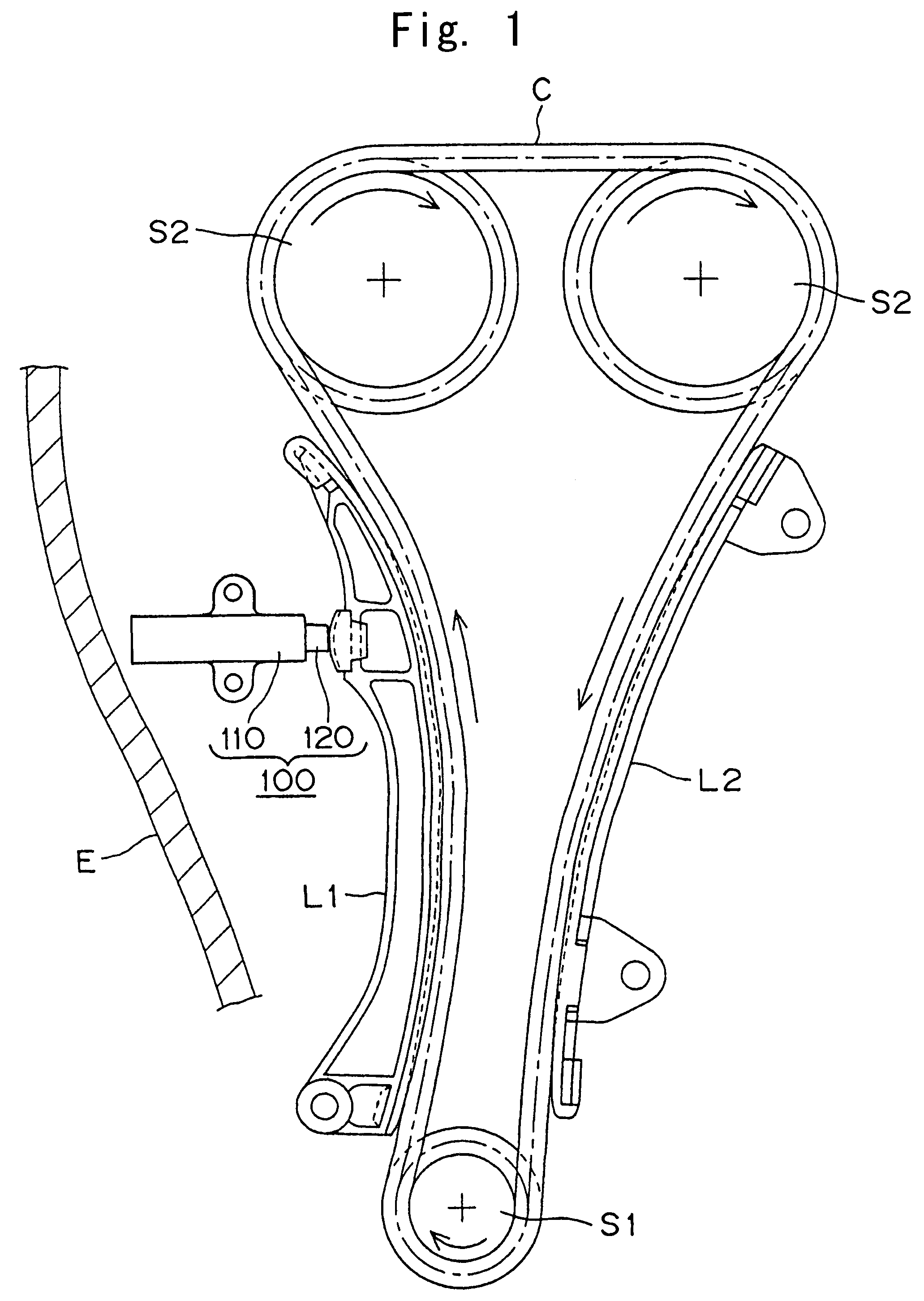
FIELD OF THE INVENTION[0001]This invention relates to a hydraulic tensioner having a check valve unit used for applying proper tension to a transmission medium such as a timing belt, a timing chain, or the like, in a vehicle engine.BACKGROUND OF THE INVENTION[0002]Hydraulic tensioners have been widely used to maintain proper tension in, and prevent vibration of, a transmission medium such as a timing chain, which transmits rotation between a crankshaft and one or more camshafts in a vehicle engine to prevent vibration generated in the travel of the medium and maintain proper tension.[0003]A typical conventional hydraulic tensioner, shown in FIG. 5, is described and depicted in Japanese Laid-open Patent Publication No. Hei-11-336855. As shown in FIG. 5, in the conventional hydraulic tensioner 500, a plunger 520 fits slidably in a plunger accommodating hole 511 formed in a housing 510, hollow interior 521, open at one end, is formed in the plunger 520, and a helical plunger-biasing sp...

Claims


Application Information

Patent Timeline
Patent Type & Authority Patents(United States)
IPC IPC(8): F16H7/08
CPCF16H7/0836F16H2007/0806F16H2007/0812F16H2007/0853F16H2007/0859
Inventor YOSHIDA, OSAMU
Owner TSUBAKIMOTO CHAIN CO
Learn More