Eureka AIR delivers breakthrough ideas for toughest innovation challenges, trusted by R&D personnel around the world.

Dual bandpass filter having serial configuration of coupled-line filters

a coupled-line filter and dual-bandpass technology, applied in the field of bandpass filters, can solve the problems of low insertion loss, signal passing through the filter has small energy, and the bandwidth at high passband in the dual-band filter is obviously not wide enough in this structure, so as to reduce noise, reduce insertion loss, and wide bandwidth

Inactive Publication Date: 2009-03-31
NAT CHIAO TUNG UNIV
View PDF2 Cites 2 Cited by
  • Summary
  • Abstract
  • Description
  • Claims
  • Application Information

AI Technical Summary

Benefits of technology

[0004]The main purpose of the present invention is to use impedance series to obtain a finite transmission zero in order to suppress noise and to obtain a wide bandwidth at a high passband and a low insertion loss at the passband.

Problems solved by technology

Although the prior art uses pairs of resonators and obtains two mutually-coupled pairs of resonators to obtain dual response and a finite transmission zero is obtained between two passbands through a transmission line connecting the two pairs of resonators, the bandwidth at high passband in the dual bandpass filter is obviously not wide enough in this structure while having high insertion loss.
As a result, signals passing this filter have small energy and the performance of the whole circuit is not good.
Hence, the prior art does not fulfill users' requests on actual use.

Method used


Image

  • Dual bandpass filter having serial configuration of coupled-line filters
  • Dual bandpass filter having serial configuration of coupled-line filters
  • Dual bandpass filter having serial configuration of coupled-line filters

Examples


Embodiment Construction

[0014]The following descriptions of the preferred embodiments are provided to understand the features and the structures of the present invention.

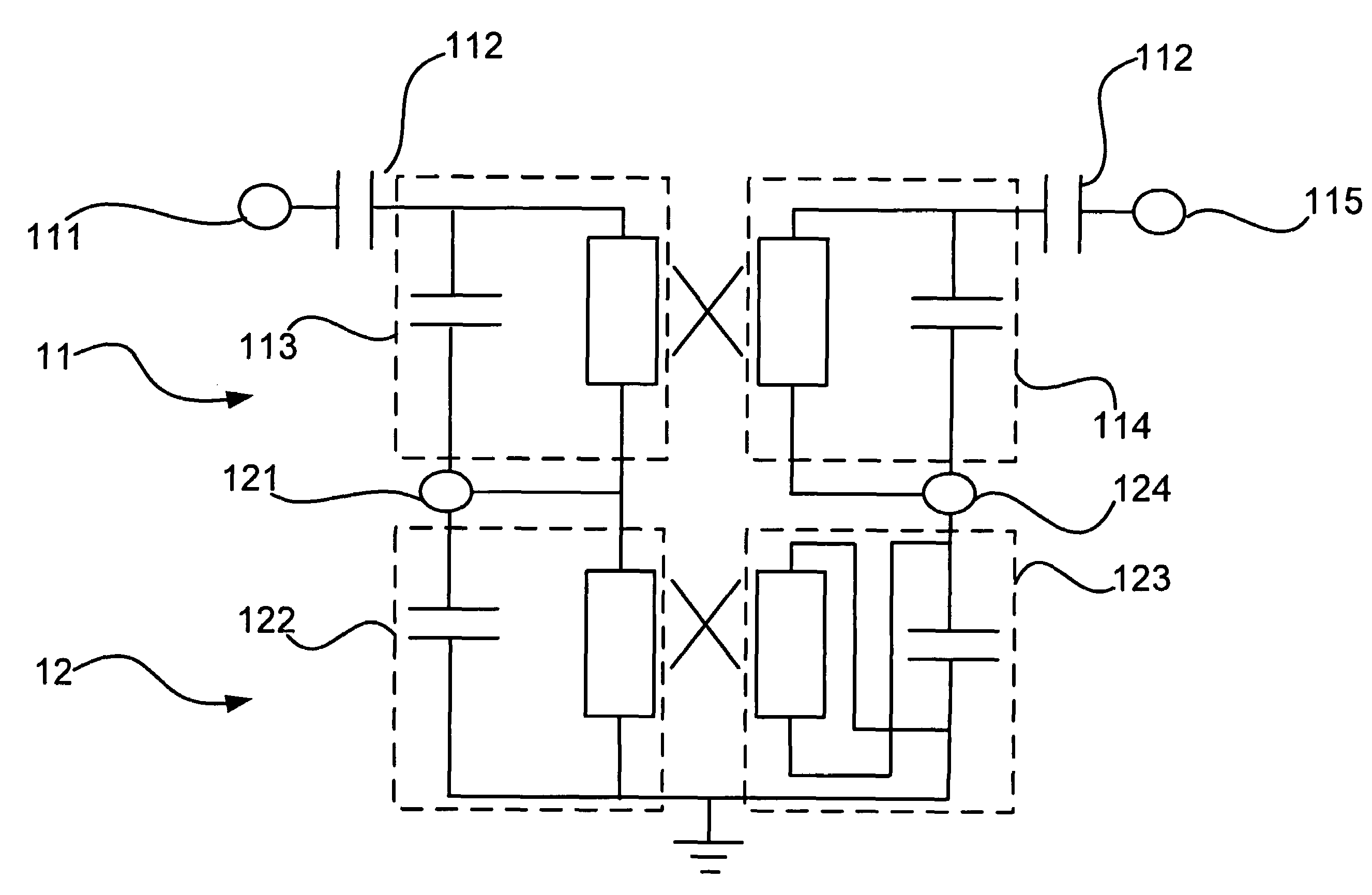
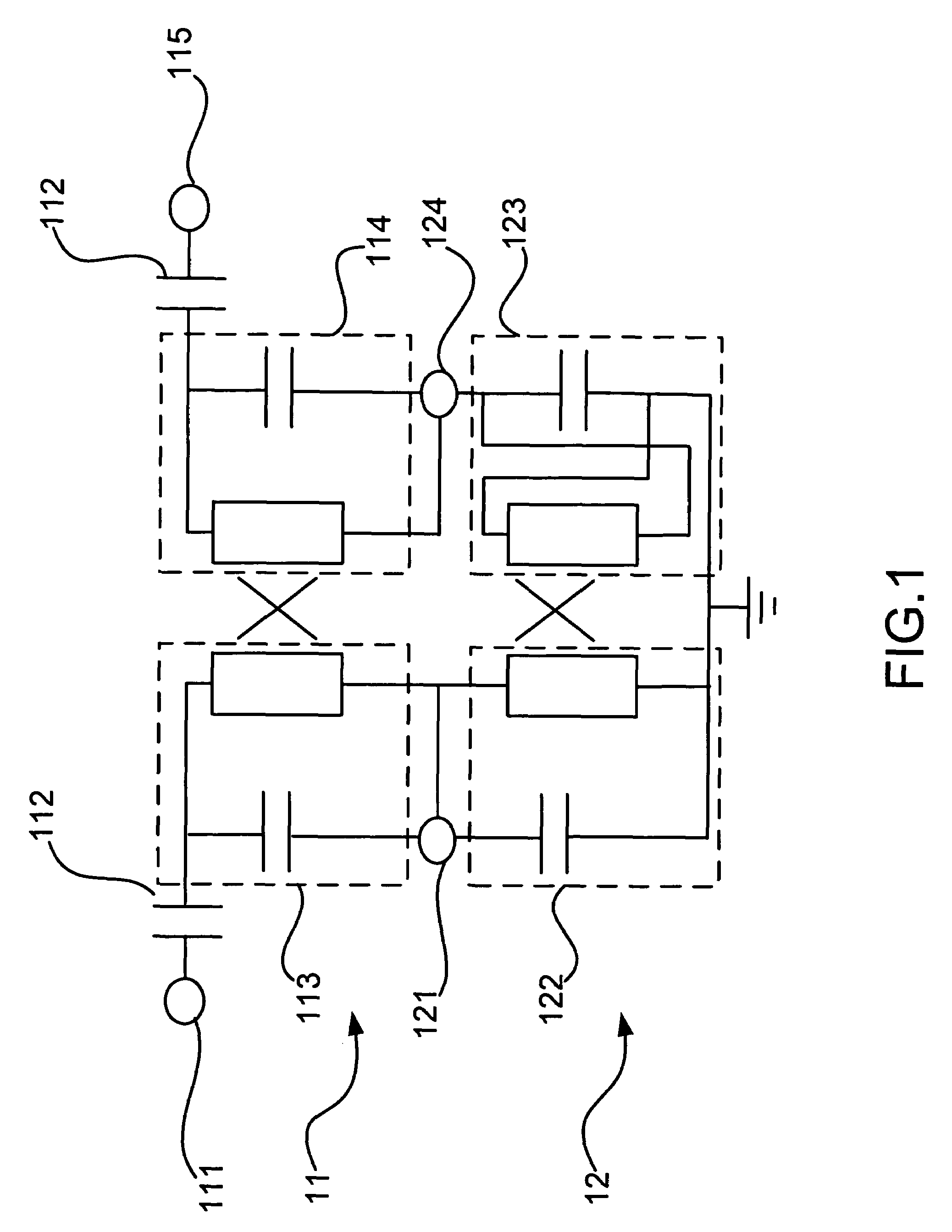
[0015]Please refer to FIG. 1, which is a structural view showing the circuit of a first preferred embodiment according to the present invention. As shown in the figure, the present invention is a dual bandpass filter having a serial configuration of coupled-line filters, comprising a first second-order inductive bandpass filter 11 and a first second-order capacitive bandpass filter 12.

[0016]The first second-order inductive bandpass filter 11 has a first input 111 connected with a direct-current (DC) capacitor 112 connecting to a first resonator 113; the first resonator 113 is coupled to a second resonator 114 in a way of a mutual inductive coupling; and, the second resonator 114 is connected with a first DC capacitor 112 connecting to a first output 115. Therein, an end of the first resonator 113 and an end of the second resonator 114 are ...


PUM


Abstract

Two second-order bandpass filter are connected serially to obtain a dual bandpass filter. One is inductive and the other is capacitive. One has a low passband and the other has a high passband. Between them, a finite transmission zero is formed to suppress noise. The present invention achieves a passband as wide as 1 gigahertz so that it can be applied to a wireless local network, communication equipments and electronic devices.

Description

FIELD OF THE INVENTION[0001]The present invention relates to a bandpass filter; more particularly, relates to serially connecting a second-order inductive / capacitive bandpass filter at low passband and a second-order capacitive / inductive bandpass filter at high passband to obtain a dual bandpass filter.DESCRIPTION OF THE RELATED ART[0002]A prior art of a dual bandpass filter is proclaimed in Taiwan, having a first passband and a second passband corresponding to a first frequency and a second frequency. The dual bandpass filter comprises a first pair of resonators including a first resonator and a second resonator, the first resonator and the second resonator sharing a first grounding transmission line, the grounding transmission line grounding at an end, the first resonator and the second resonator coupling with each other by the grounding transmission line; a second pair of resonators including a third resonator and a fourth resonator, the third resonator and the fourth resonator s...

Claims


Application Information

Patent Timeline
Patent Type & Authority Patents(United States)
IPC IPC(8): H03H7/00H03H7/01
CPCH01P1/20
Inventor CHUNG, SHYH-JONGLIN, KE-CHIANGCHANG, CHUN-FU
Owner NAT CHIAO TUNG UNIV
Why Eureka
Eureka Blog
Learn More