
Display device

a technology of display device and display case, which is applied in the direction of machine supports, instruments, cabinet/cabinet/drawer, etc., can solve the problems of undesirable thickness and weight increase undesirable assembly process of related art flat display device, so as to reduce the total thickness and weight of the display device, improve the installation structure, and improve the effect of installation structur

Active Publication Date: 2009-03-24
LG ELECTRONICS INC
View PDF17 Cites 22 Cited by
  • Summary
  • Abstract
  • Description
  • Claims
  • Application Information

AI Technical Summary

Benefits of technology

The present invention is a display device that solves problems of being too thick and heavy. It has an improved installation structure for a circuit board, making it easier to install and reducing the overall weight. The display device includes a display module, a circuit board, and a fixing plate. The circuit board is either inserted into the fixing plate through elastic deformation of the fixing plate or fixed to the fixing plate through elastic deformation of the fixing plate. This results in a thinner and lighter display device.

Problems solved by technology

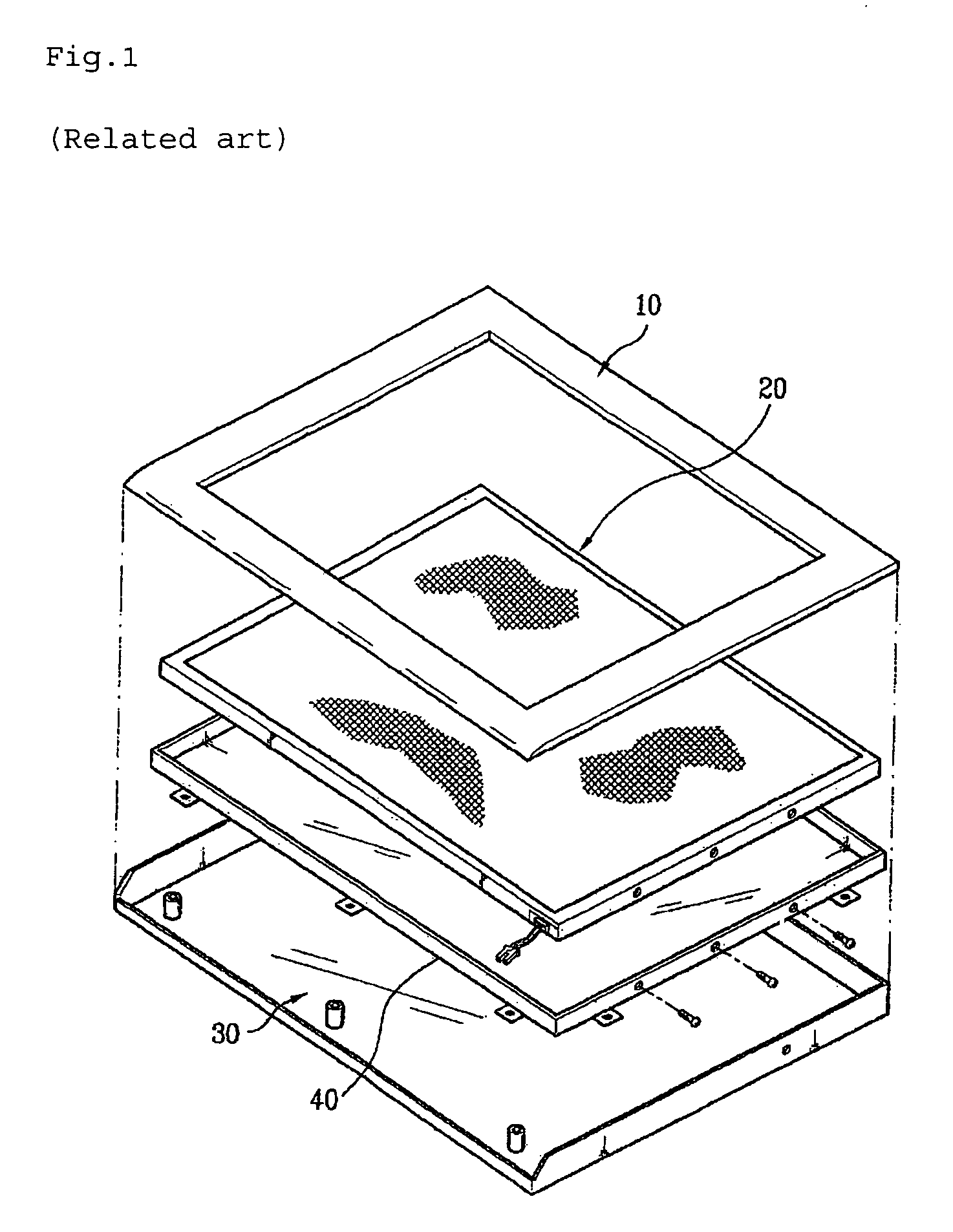
The related art flat display device undesirably has increased thickness and weight because it uses a thick metallic frame 40.
Further, the related art flat display device undesirably requires a complicated assembly process because the circuit board 41 must be fixed to the frame 40 with a fixing member such as a screw.

Method used


Image

  • Display device
  • Display device
  • Display device

Examples


Embodiment Construction

[0022]Reference will now be made in detail to the preferred embodiments of the present invention, examples of which are illustrated in the accompanying drawings. Wherever possible, the same reference numbers will be used throughout the drawings to refer to the same or like parts.

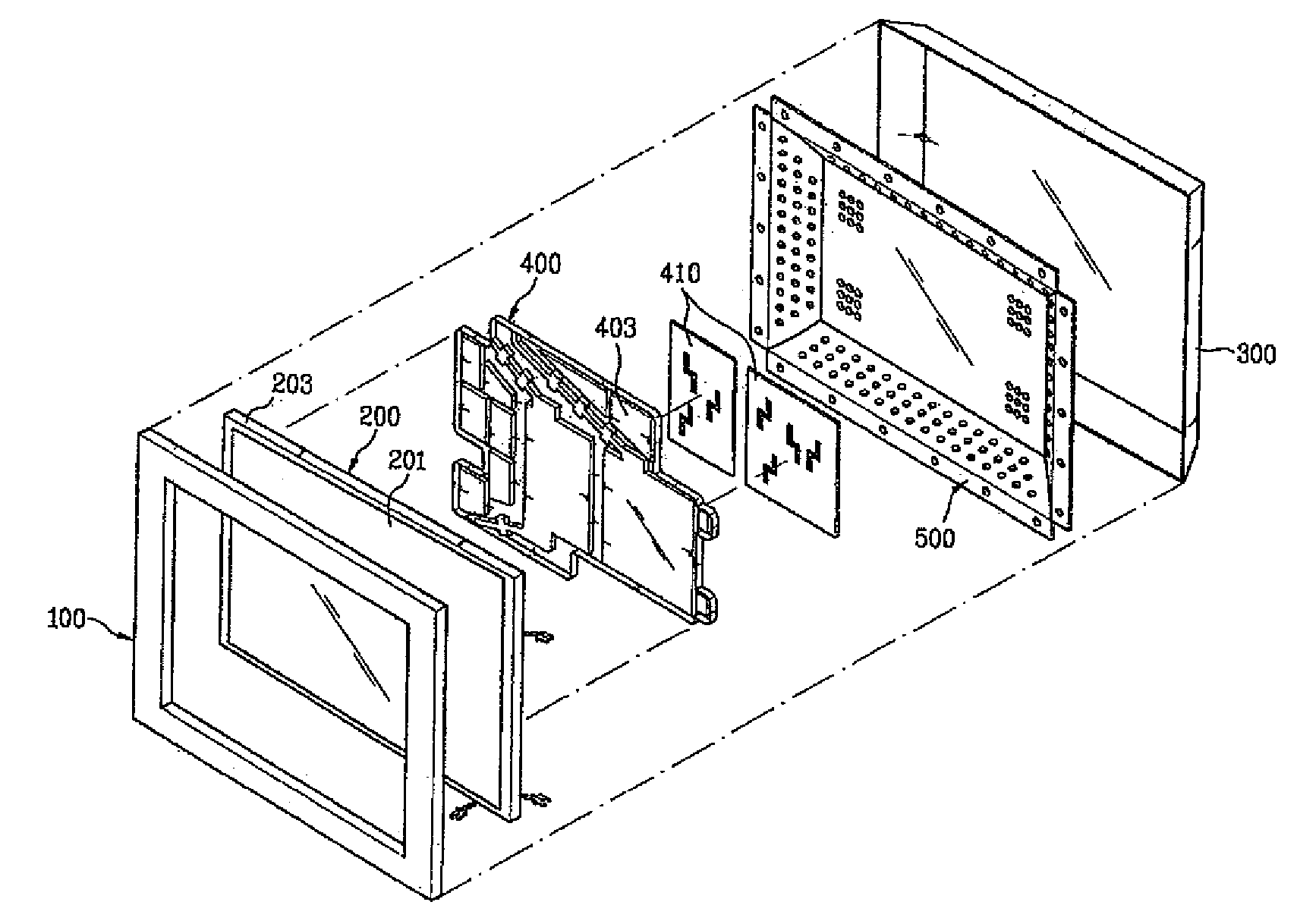
[0023]FIG. 3 is an exploded perspective view of a display device according to the present invention, and FIGS. 4 and 5 illustrate a structure in which a circuit board is fixed to a fixing plate in a display device according to the present invention.

[0024]Referring to FIG. 3, the inventive display device includes a front cover 100, a rear cover 300 connected to the front cover 100, a display module 200 disposed between the front and rear covers 100 and 300, a fixing plate 400 connected on a rear surface of the display module 200, and a circuit board 410 fixed to the fixing plate 400 and supplying a video signal and a control signal to the display module 200. The front and rear covers 100 and 300 constitute a ...


PUM

PropertyMeasurementUnit
sizeaaaaaaaaaa
insulatingaaaaaaaaaa
non-conductiveaaaaaaaaaa

Abstract

A display device is provided. The display device includes a display module for displaying a video image, a circuit board for providing a video signal and a control signal to the display module, and a fixing plate fixed on a rear surface of the display module. The circuit board is inserted into and fixed to the fixing plate through elastic deformation of a portion of the fixing plate.

Description

[0001]This nonprovisional application claims priority under 35 U.S.C. § 119(a) on Patent Application No. 10-2004-0062075 filed in Korea on Aug. 6, 2004, which is herein incorporated by reference.BACKGROUND OF THE INVENTION[0002]1. Field of the Invention[0003]The present invention relates to a display device, and more particularly, to a display device having a fixing plate for fixing a circuit board thereto for driving a display module of the display device.[0004]2. Description of the Related Art[0005]Flat display devices are used as monitors of desktop computers and also used in various electronic devices such as notebook computers, personal digital assistants (PDA) and portable phones. Examples of such flat display devices include a liquid crystal display (LCD), a plasma display panel (PDP) and a field emission display (FED).[0006]FIG. 1 illustrates a construction of a related art flat display device, and FIG. 2 illustrates a structure in which a circuit board is fixed in the relat...

Claims


Application Information

Patent Timeline
Patent Type & Authority Patents(United States)
IPC IPC(8): G06F1/16G02F1/13H01J17/49
CPCG02F1/133308G02F1/13452G02F2001/133314G02F2201/46G02F1/133314Y10S248/917Y10S248/918G02F1/1333
Inventor BAEK, JIN UK
Owner LG ELECTRONICS INC
Learn More