
Gear mounting structure for fishing reel

a technology for fishing reels and mounting structures, which is applied in fishing, applications, reels, etc., can solve the problems of a decrease in the sensitivity of the handle operation of the fisherman, the inability to adjust the sensitivity between the end of the screw shaft and the through hole of the gear, etc., and achieve the effect of no loss of sensitivity

Active Publication Date: 2009-03-10
SHIMANO INC
View PDF14 Cites 2 Cited by
  • Summary
  • Abstract
  • Description
  • Claims
  • Application Information

AI Technical Summary

Benefits of technology

The present invention provides a gear mounting structure for a fishing reel that reduces instability and loss of sensitivity related to the operation of the handle by a fishman. This is achieved by using a flexible ring member between the mounting part of a screw shaft and the mounting cavity of the gear component, which prevents instability between the mounting cavity and the mounting part when the mounting part is non-rotational relative to the gear component. The gear mounting structure can be easily positioned and locked in place, and offers a high degree of concentricity and evenness in the winding of fishing line on the spool.

Problems solved by technology

However, since only the end of the screw shaft engages the through hole of the gear, some instability is generated between the end of the screw shaft and the through hole of the gear.
When the gears are rotated in conjunction with the rotation of the handle, and particularly when the rotational torque of the screw shaft changes as the fishing line guide part and slider reverse direction at the end positions of the screw shaft, there is an increased instability between the end of the screw shaft and the through hole of the gear so as to cause a concern about a decrease in sensitivity in the handle operation by the fisherman.

Method used


Image

  • Gear mounting structure for fishing reel
  • Gear mounting structure for fishing reel
  • Gear mounting structure for fishing reel

Examples


second embodiment

[0043]Referring now to FIG. 4, a gear mounting structure in accordance with a second embodiment will now be explained. In view of the similarity between the first and second embodiments, the parts of the second embodiment that are identical to the parts of the first embodiment will be given the same reference numerals as the parts of the first embodiment. Moreover, the descriptions of the parts of the second embodiment that are identical to the parts of the first embodiment may be omitted for the sake of brevity.

[0044]Although the spinning reel oscillating mechanism is used as an example in the first embodiment, the present invention is also applicable to the level winding mechanism of dual bearing reels.

[0045]Referring to FIG. 4, the second embodiment of the present invention is applied to a dual bearing reel. The dual bearing reel includes a reel main body 102, a spool rotating handle 101 and a drag adjusting stay drag 103. The spool rotating handle 101 is disposed on a side of th...

third embodiment

[0048]Referring now to FIG. 5, a gear mounting structure in accordance with a third embodiment will now be explained. In view of the similarity between the first and third embodiments, the parts of the third embodiment that are identical to the parts of the first embodiment will be given the same reference numerals as the parts of the first embodiment. Moreover, the descriptions of the parts of the third embodiment that are identical to the parts of the first embodiment may be omitted for the sake of brevity.

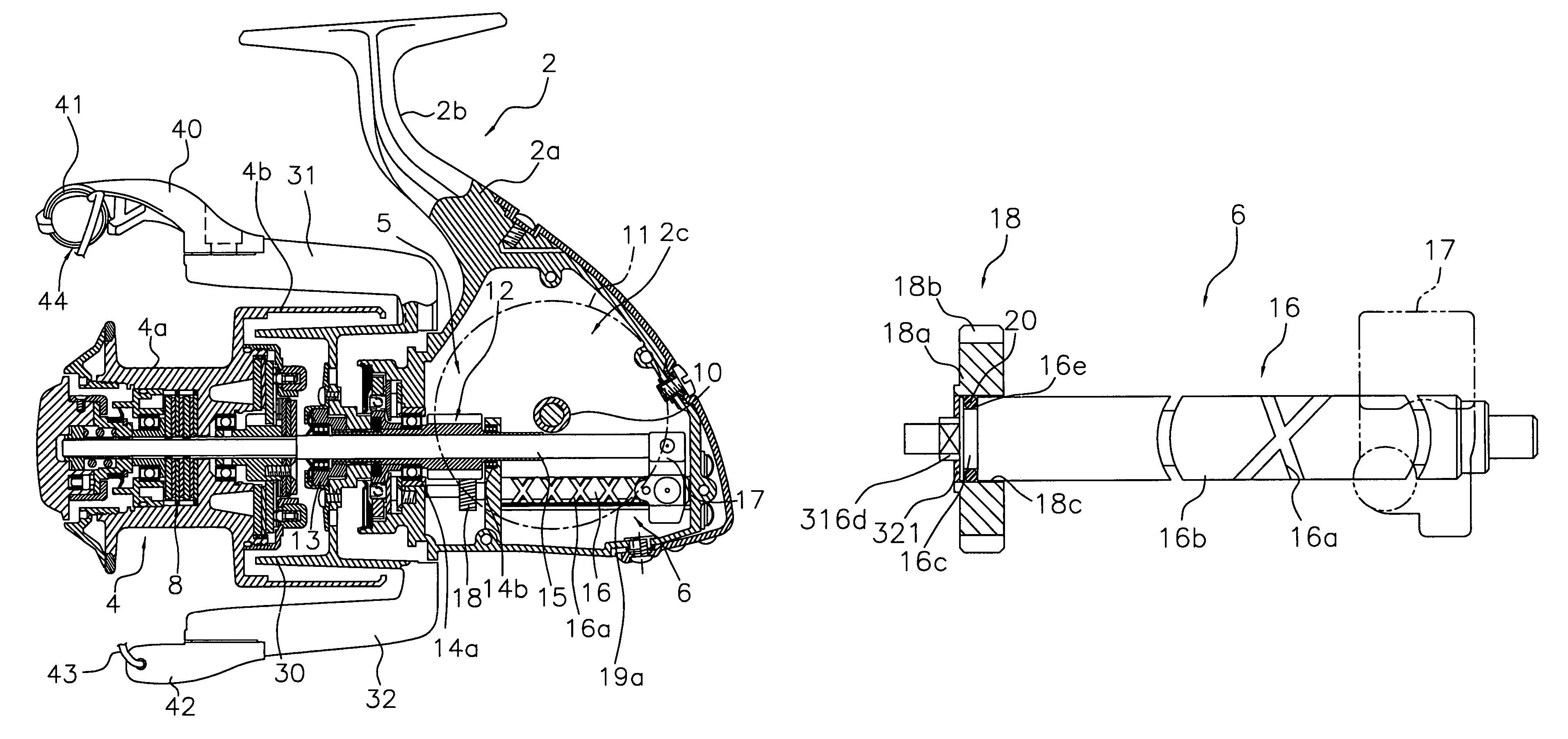
[0049]In the first embodiment, the mounting channel 16e for installing the ring member 20 is formed on the screw shaft 16. In the third embodiment, the mounting channel 16e is omitted as shown in FIG. 5. A mounting part 216c for a flexible ring member 220 has an outer diameter that is the same as the outer diameter of the shaft body 16b.

fourth embodiment

[0050]Referring now to FIG. 6, a gear mounting structure in accordance with a fourth embodiment will now be explained. In view of the similarity between the first and fourth embodiments, the parts of the fourth embodiment that are identical to the parts of the first embodiment will be given the same reference numerals as the parts of the first embodiment. Moreover, the descriptions of the parts of the fourth embodiment that are identical to the parts of the first embodiment may be omitted for the sake of brevity.

[0051]In the first embodiment, the connecting cavity 18d having a non-circular cross section in the axial direction is formed on the intermediate gear 18 so that the intermediate gear 18 and the screw shaft 16 are non-rotational when the connecting part 16d engages the connecting cavity 18d. In the fourth embodiment, the connecting cavity 18d is omitted and the intermediate gear 18 and the screw shaft 16 are rendered non-rotational by a baffle washer 321 provided separate fr...


PUM


Abstract

A gear mounting structure for a fishing reel includes a screw shaft, a gear component and a ring member. The screw shaft has a shaft body, a spiral groove and a mounting part provided at an end of the shaft body. The spiral groove has a crossing point on an exterior circumference of the shaft body. The gear component has a gear body, a plurality of gear teeth and a mounting cavity. The gear teeth are formed in a circumferential direction along an exterior circumference of the gear body. The mounting cavity is for non-rotatably mounting the mounting part. The ring member has an elastic body interposed between the mounting part and the mounting cavity.

Description

CROSS-REFERENCE TO RELATED APPLICATIONS[0001]This application claims priority under 35 U.S.C. § 119 to Japanese Patent Application No. 2006-012885 filed on Jan. 20, 2006. The entire disclosure of Japanese Patent Application No. 2006-012885 is hereby incorporated herein by reference.BACKGROUND OF THE INVENTION[0002]1. Field of the Invention[0003]The present invention generally relates to a gear mounting structure. More specifically, the present invention relates to a gear mounting structure for mounting a shaft to a gear in a reciprocating movement mechanism of a fishing reel.[0004]2. Background Information[0005]Fishing reels mainly include spinning reels and dual bearing reels. This type of fishing reel has a reel main body mounted on a fishing rod and a spool provided in the reel main body to wind fishing line. In dual bearing reels, the spool is supported on the reel main body so as to be freely rotatable. The spool is provided with a level winding mechanism for evenly winding the...

Claims


Application Information

Patent Timeline
Patent Type & Authority Patents(United States)
IPC IPC(8): A01K89/01
CPCA01K89/0114A01K89/015A01K89/01
Inventor KITAJIMA, KEIGO
Owner SHIMANO INC
Learn More