
Electro-static discharge protection circuit and semiconductor device having the same

a protection circuit and electrostatic discharge technology, applied in the direction of emergency protective circuit arrangements, emergency protective arrangements for limiting excess voltage/current, emergency protective arrangements for reducing excess voltage/current, etc., can solve the problems of increasing chip capacitance and chip capacitance decreas

Active Publication Date: 2009-03-03
LAPIS SEMICON CO LTD
View PDF2 Cites 6 Cited by
  • Summary
  • Abstract
  • Description
  • Claims
  • Application Information

AI Technical Summary

Benefits of technology

The present invention provides an electro-static discharge protection circuit that includes a thyristor rectifier circuit and a thyristor mode ensuring circuit. The thyristor mode ensuring circuit triggers the thyristor rectifier circuit into a thyristor mode by a surge current applied to a signal input / output section, which allows the circuit to protect the internal circuitry from the surge current. The technical effect of this invention is to provide a reliable and effective protection against electro-static discharge for sensitive electronic components.

Problems solved by technology

Fewer N-well regions will decrease the total stray capacitances between the N-well regions of the other electro-static discharge protection circuits and the substrate, which in turn will result in a decrease in the chip capacitance.
More N-well regions will increase the total stray capacitances between the N-well regions of the other electro-static discharge protection circuits and the substrate, which in turn will result in an increase in the chip capacitance.

Method used


Image

  • Electro-static discharge protection circuit and semiconductor device having the same
  • Electro-static discharge protection circuit and semiconductor device having the same
  • Electro-static discharge protection circuit and semiconductor device having the same

Examples


first embodiment

(1) First Embodiment

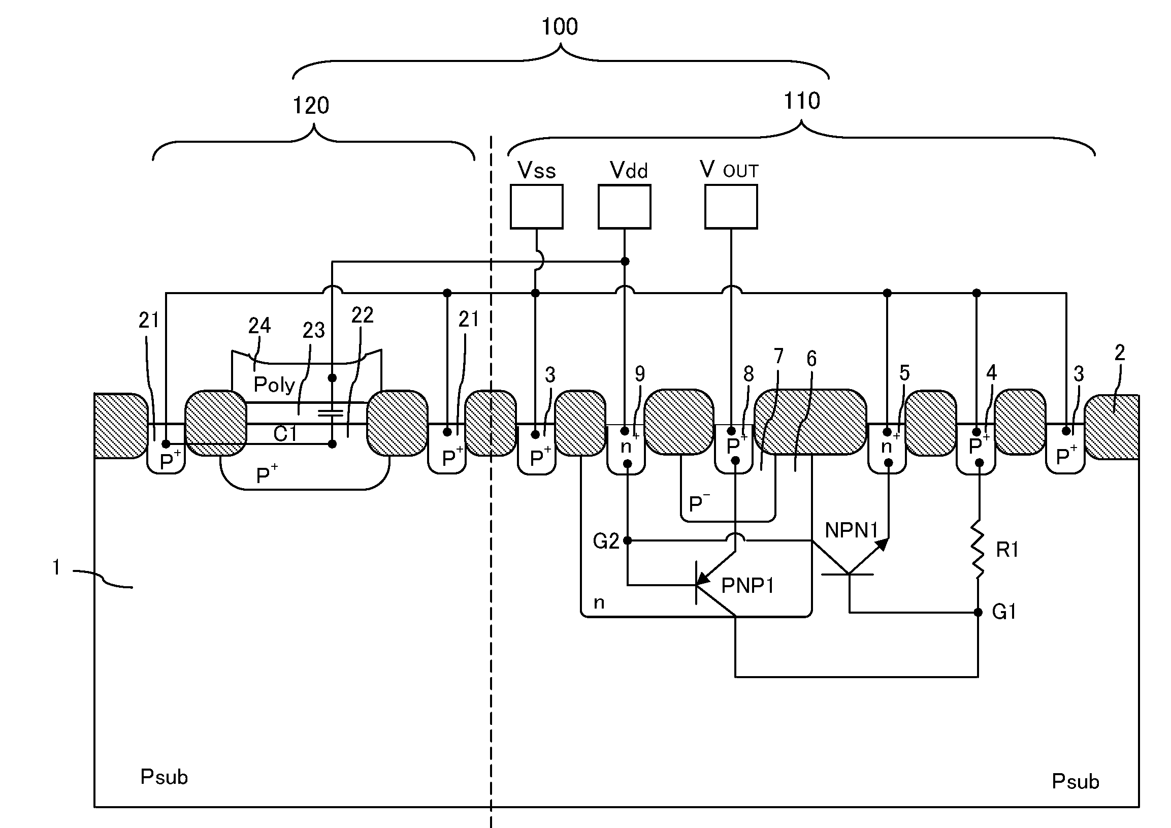
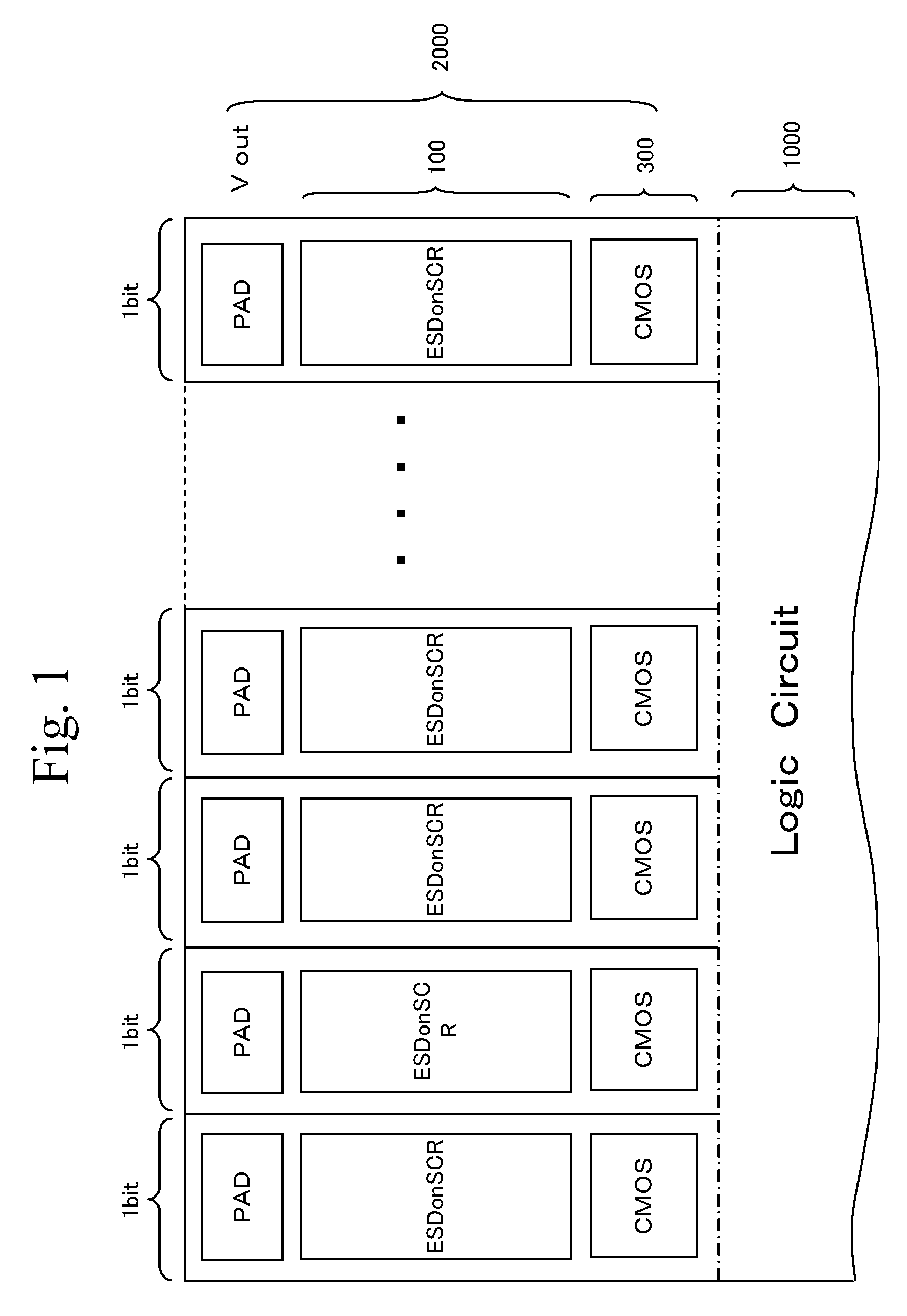
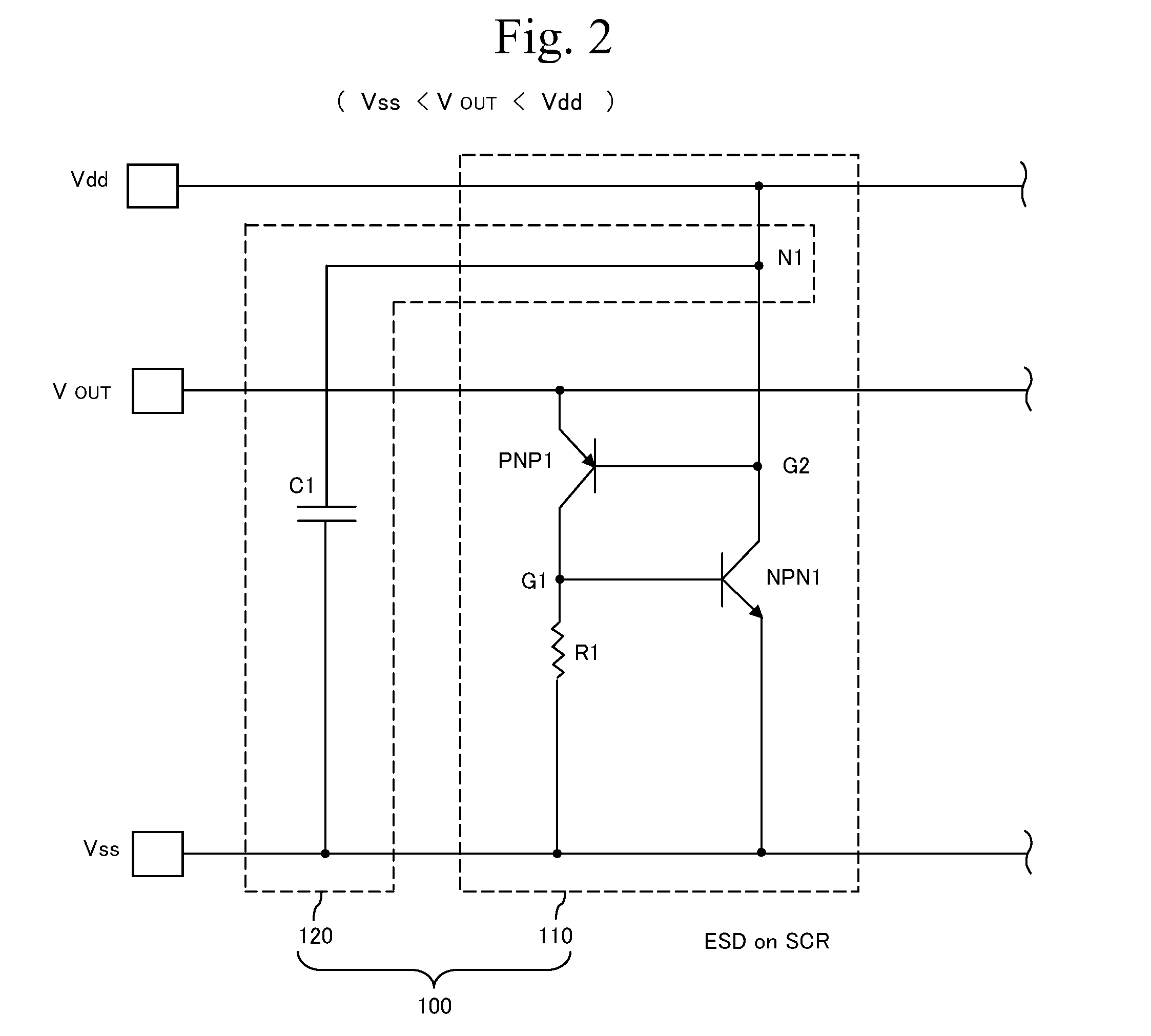
[0046]According to a first embodiment, an electro-static discharge protection circuit 100 is provided which includes a thyristor mode ensuring circuit that, independently of the number of input / output signal bits, ensures that the thyristor rectifier circuit will be triggered into a thyristor mode by a surge current induced by electro-static discharge (ESD) applied to an input / output pad PAD. To ensure that the thyristor rectifier circuit is triggered into a thyristor mode by a surge current, the thyristor mode ensuring circuit needs to fulfill the function of keeping a snapback voltage at or under an acceptable upper limit. Hence the thyristor mode ensuring circuit functions both to ensure that a thyristor mode will be triggered, and to keep a snapback voltage at or under an acceptable upper limit.

[0047]FIG. 2 is an equivalent circuit view which shows each of the plurality of electro-static discharge protection circuits in FIG. 1. Each electro-static discharge p...

second embodiment

(2) Second Embodiment

[0097]According to a second embodiment, an electro-static discharge protection circuit 100 is provided which includes a thyristor mode ensuring circuit that, independently of the number of input / output signal bits, ensures that a thyristor rectifier circuit will be triggered into a thyristor mode by a surge current induced by electro-static discharge (ESD) applied to an input / output pad PAD. To ensure that a thyristor rectifier circuit will be triggered into a thyristor mode by a surge current, the thyristor mode ensuring circuit needs to fulfill the function of keeping a snapback voltage at or under an acceptable upper limit. Hence the thyristor mode ensuring circuit both functions to ensure that a thyristor mode will be triggered, and to keep a snapback voltage at or under an acceptable upper limit.

[0098]FIG. 10 is an equivalent circuit view to show each of the plurality of electro-static discharge protection circuits in FIG. 1. Each electro-static discharge p...

third embodiment

(3) Third Embodiment

[0148]According to a third embodiment, an electro-static discharge protection circuit 100 is provided which includes a thyristor mode ensuring circuit that, independently of the number of input / output signal bits, ensures that a thyristor rectifier circuit will be triggered into a thyristor mode by a surge current induced by electro-static discharge (ESD) applied to an input / output pad PAD. To ensure that a thyristor rectifier circuit will be triggered into a thyristor mode by a surge current, the thyristor mode ensuring circuit needs to fulfill the function of keeping a snapback voltage at or under an acceptable upper limit. Hence the thyristor mode ensuring circuit both functions to ensure that a thyristor mode will be triggered, and to keep a snapback voltage at or under an acceptable upper limit.

[0149]FIG. 18 is an equivalent circuit view which shows each of the plurality of electro-static discharge protection circuits in FIG. 1. Each electro-static discharge...


PUM


Abstract

An electro-static discharge protection circuit includes a thyristor mode ensuring circuit and a thyristor rectifier circuit. The thyristor mode ensuring circuit includes a capacitive element connected between a higher potential line and a lower potential line, and ensures a constant and sufficient capacity independently of the number of input / output signal bits, even when the number of input / output signal bits is a theoretical minimum, i.e. 1, so that a surge current induced by electro-static discharge (ESD) applied to an output pad is injected into the first capacitive element to charge it. Thus, by means of the current caused by the surge current, the thyristor rectifier circuit is triggered into a thyristor mode, which allows the surge current to flow to the lower potential line through the thyristor rectifier circuit, protecting circuitry against the surge current.

Description

BACKGOUND OF THE INVENTION[0001]1. Field of the Invention[0002]The present invention relates to an electro-static discharge protection circuit to protect internal circuitry from electro-static discharge (ESD).[0003]2. Description of the Related Art[0004]An electro-static discharge protection circuit is established between an input / output terminal and internal circuitry of a semiconductor integrated circuit to protect the internal circuitry against a surge current caused by electro-static discharge (ESD) applied to the input / output terminal. As used herein, the term “internal circuitry” means circuits to be protected against electro-static discharge (ESD) by an electro-static discharge protection circuit.[0005]Electro-static discharge protection circuits using a rectifier with thyristors are known in the art, and one such circuit was disclosed in the 2004 EOS / ESD Symposium, “ESD Protection Solution for High Voltage Technologies”, (C. Principle of ESD-on-SCR). The electro-static disch...

Claims


Application Information

Patent Timeline
Patent Type & Authority Patents(United States)
IPC IPC(8): H01L29/74
CPCH01L27/0262
Inventor KURODA, TOSHIKAZUHAYASHI, HIROKAZUFUKUDA, YASUHIRO
Owner LAPIS SEMICON CO LTD
Learn More