
Holographic adaptive optic system

a technology of adaptive optics and optics, applied in the field of adaptive optics systems, can solve the problems of limiting resolution, degrading image quality, blurring image,

Inactive Publication Date: 2009-02-24
AIR FORCE US SEC THE THE
View PDF2 Cites 8 Cited by
  • Summary
  • Abstract
  • Description
  • Claims
  • Application Information

AI Technical Summary

Benefits of technology

"The patent describes a system that uses holographic optics to correct the wavefront of a light. It includes a device with multiple pixels that can adjust the phase of the light to match a reference wavefront. The system also has a sensor that measures the wavefront of the light and provides feedback to the phase correction device. This feedback helps to fine-tune the correction to match the actual wavefront of the light. The system can be controlled by individual control connectors that adjust the phase correction device based on the intensity of the light beams. Overall, this technology allows for more precise and accurate correction of the light wavefront, which can be useful in various applications such as optical imaging and laser systems."

Problems solved by technology

In many cases, however, imaging is degraded due to distortions of the phase of the final wavefront.
For example, when viewing scenes through the atmosphere, variations in refractive index due to pockets of hot and cold air can distort a wavefront significantly, blurring images and limiting the resolution.
Imperfect or misaligned optics can also result in phase distortions which will similarly degrade image quality.
Generally this process is slowed due to computational loads imposed by the detection and computational methods as well as requirements of control software to take the “sensed” data and convert this into “correction” signals for the corrective optic.
For this reason there are limits on the speeds that adaptive correction can achieve in real life systems.
In cases of extremely rapid phase changes such as those experienced in looking through airflows around airplanes, conventional adaptive optics may not be fast enough to provide acceptable correction.
Even if this wavefront sensor were inserted into a conventional adaptive optics system, the data transfer and control software bottlenecks would slow down the correction process considerably.

Method used


Image

  • Holographic adaptive optic system
  • Holographic adaptive optic system
  • Holographic adaptive optic system

Examples


Embodiment Construction

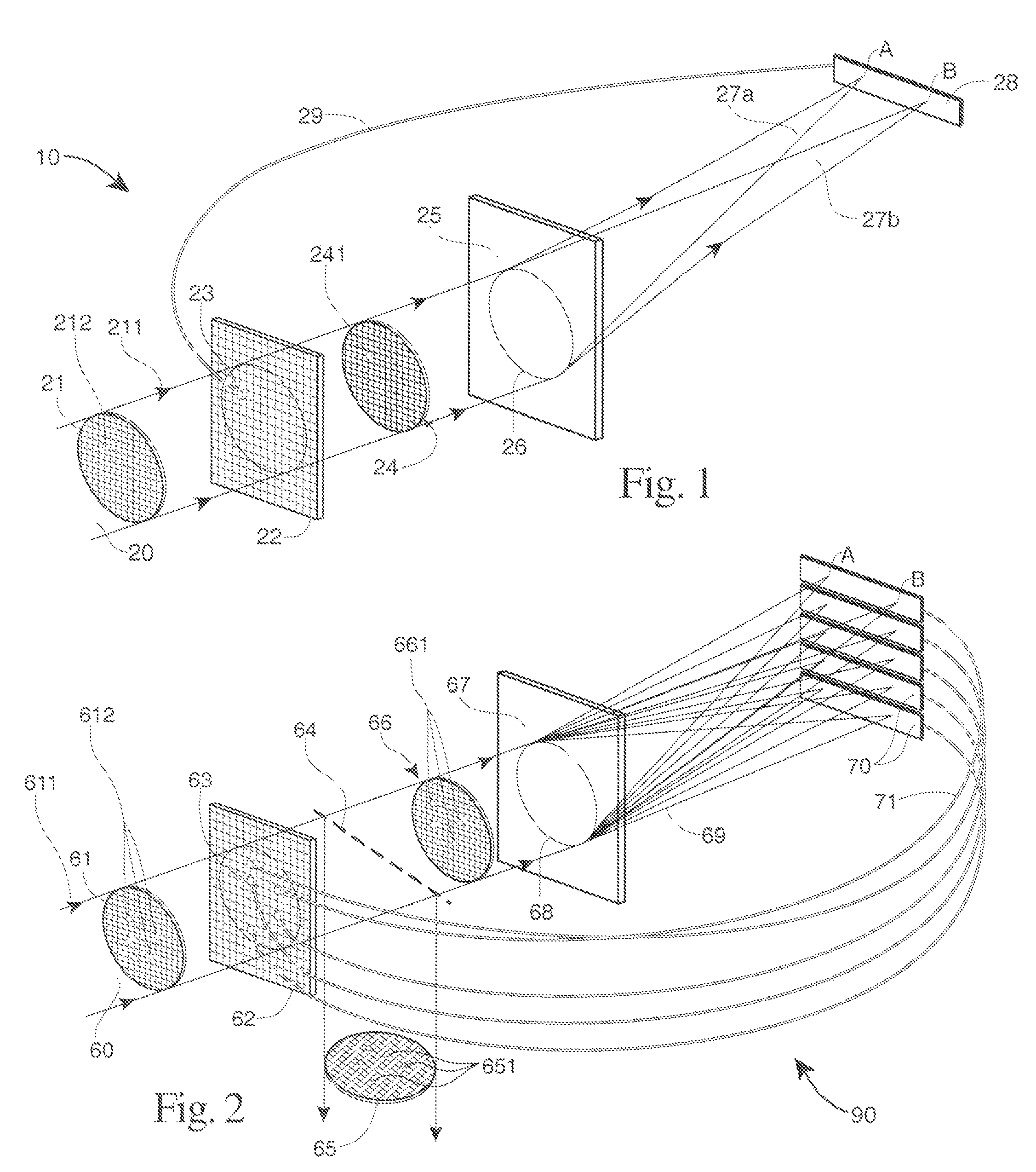
[0010]The holographic adaptive optics system consists of three major parts, a holographic wavefront sensor, a detector to register the locations of reconstructed beams, and a device for producing phase corrections to a wavefront.

[0011]The first part of the adaptive optics system involves a holographic wavefront sensor (HWFS) described in patent application Ser. No. 11 / 138,727 titled “Holographic Wavefront Sensor” and incorporated herein by reference. This wavefront sensor analyzes an entire wavefront at once (a so-called modal detector) using a hologram. The wavefront sensor may consist of a diffractive optical element such as a multiplexed hologram which may be fabricated or programmed in advance with all aberrations to be corrected. In operation, a wavefront incident on the hologram is divided up into multiple output beams according to the presence and strength of particular aberrations present in the input.

[0012]The HWFS may operate at any wavelength in the electromagnetic spectr...


PUM


Abstract

A holographic adaptive optic system for correcting the wavefront of a light. A phase correction device with a plurality of pixels in the path of the light. A holographic wavefront sensor in the path providing a pair of reconstruction beams for each phase correction device pixel. The relative intensity of the two beams being proportional to the amount of aberration present in the initial beam. A detector that measures the relative intensity of the pair of reconstructed beams. The detector connected by at least one individual control connector to the relevant pixel in the phase correction device. The individual control connectors controlling the phase correction device based upon the relative intensity between the two reconstruction beams to reduce the wavefront aberration.

Description

[0001]The invention described herein may be manufactured and used by or for the Government of the United States for all governmental purposes without the payment of any royalty.BACKGROUND OF THE INVENTION[0002]The invention relates to an adaptive optics system incorporating a holographic wavefront sensor.[0003]A highly spherical (or flat) wavefront is required for diffraction-limited imaging, and peak-to-valley phase errors of less than a quarter of a wavelength are generally preferred. In many cases, however, imaging is degraded due to distortions of the phase of the final wavefront. For example, when viewing scenes through the atmosphere, variations in refractive index due to pockets of hot and cold air can distort a wavefront significantly, blurring images and limiting the resolution. Imperfect or misaligned optics can also result in phase distortions which will similarly degrade image quality.[0004]Adaptive optics is a technique which can correct for these aberrations. The proce...

Claims


Application Information

Patent Timeline
Patent Type & Authority Patents(United States)
IPC IPC(8): G01B9/02
CPCG01J9/02G02B5/32G02B26/06G03H1/0005G02B26/0808G03H1/2294
Inventor ANDERSEN, GEOFF P.
Owner AIR FORCE US SEC THE THE
Learn More