
Signal receiving method in MIMO system and device therefor

a technology of mimo and receiving method, which is applied in the field of receiving method in mimo system and device therefor, can solve the problems of low decoding performance, large computational effort, and noise in each receiving antenna, and achieve excellent decoding performance and suppress the complexity of decoding processing.

Inactive Publication Date: 2009-02-17
FUJITSU LTD
View PDF9 Cites 19 Cited by
  • Summary
  • Abstract
  • Description
  • Claims
  • Application Information

AI Technical Summary

Benefits of technology

[0036]The objective of the present invention is to obtain high decoding performance while suppressing the complexity of the decoding processing within a receiving device wherein signals are received by using a plurality of antennas.
[0038]In the receiving device, processing to newly estimate transmitted symbols is repeatedly performed, according to the information indicating the likelihood of the estimated transmitted symbols. Therefore, if the number of repetition is increased, the estimation accuracy of the transmitted symbol becomes higher.
[0040]According to the present invention, excellent decoding performance can be obtained using an algorithm wherein the complexity of the decoding processing is suppressed, in a receiving device wherein the signals are received by using a plurality of antennas.

Problems solved by technology

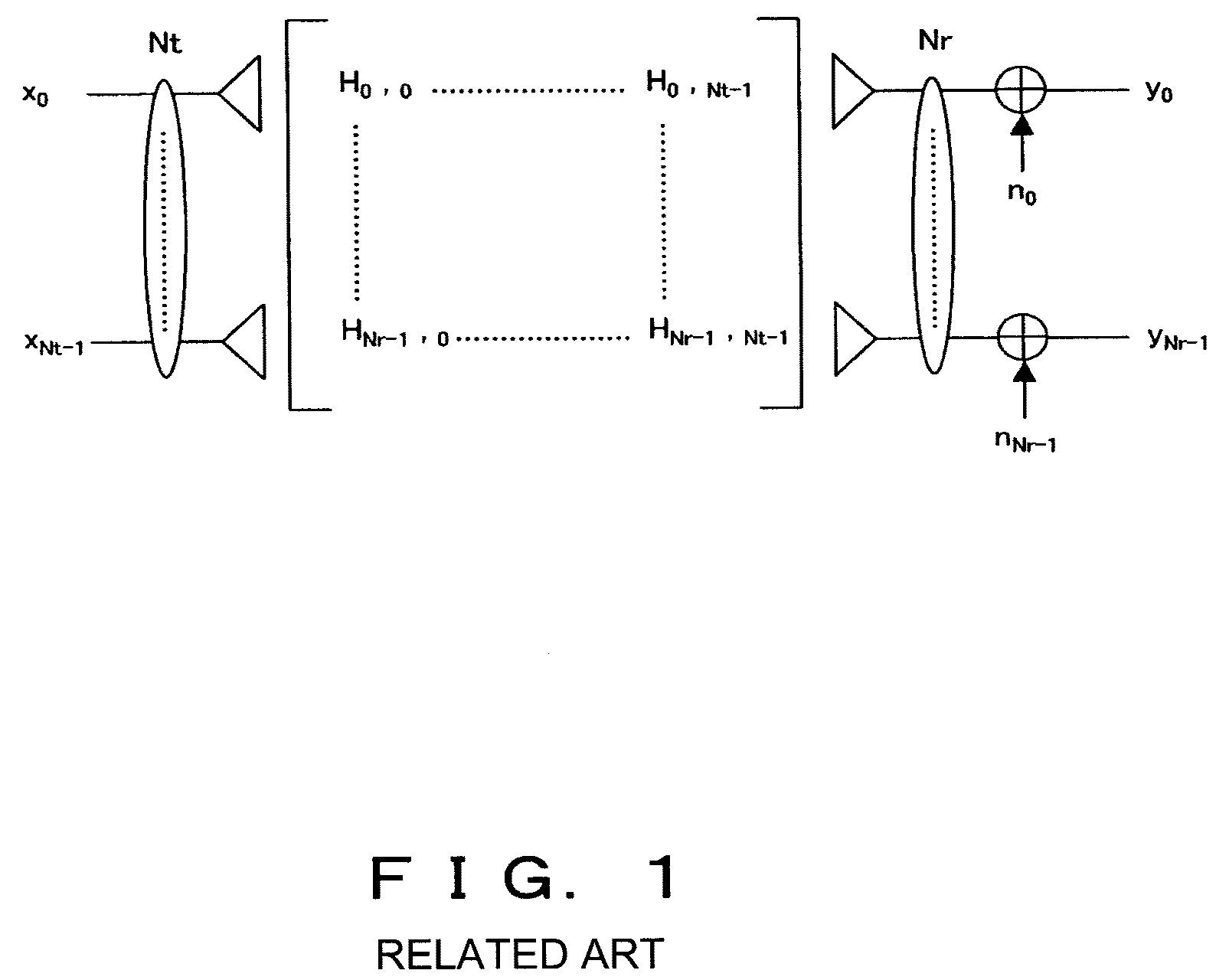
Furthermore, “n” is noise in each receiving antenna.
However, in this algorithm, since the transmitted vectors estimated from the received signals and all possible transmitted vectors must be compared, a problem exists in that the computational effort becomes very large.
If the afore-mentioned five conventional technologies are applied to the MIMO system, the following problem occurs.
Namely, in the Zero Forcing algorithm and MMES algorithm, the estimation accuracy of the transmitted symbol is low, resulting in low decoding performance.
However, the calculations of these algorithms are complicated and the load to the receiving device is heavy.

Method used


Image

  • Signal receiving method in MIMO system and device therefor
  • Signal receiving method in MIMO system and device therefor
  • Signal receiving method in MIMO system and device therefor

Examples


embodiment 1

[0137]In Embodiment 1, the algorithm according to the present invention is applied to MIMO-OFDM system. The OFDM is, for example, described in the Document 5 (R. Van Nee and R. Prasad, “OFDM For Wireless Multimedia Communications”, Artech House Publishers, 2000) and the Document 6 (L. J. Cimini, “Analysis and simulation of digital mobile channel using orthogonal frequency division multiple access”, IEEE trans. Comm., pp. 665-675, 1995), and the MIMO-OFDM is described in the Document 7 (A. Van Zeist and al., “Implementation of a MIMO OFDM-based wireless LAN system”, IEEE Trans. Signal. Process. 52, No 2, 2004, pp. 483-494). Here, the outlines are described.

[0138]OFDM is a technology which realizes high-speed transmission by lowering the rate of each sub-carrier and increasing the number of low-rate sub-carriers. Frequency bandwidth is divided into a plurality of small ranges which are each used as sub-carries. Sub-carriers are orthogonal to each other. In order to obtain this propert...

embodiment 2

[0157]In Embodiment 2, the algorithms according to the present invention are used in a multi-carrier CDMA system. The multi-carrier CDMA technology is incorporated into the OFDM modulation for multi-access. In addition, the multi-carrier CDMA is described, for example, in the Document 8 (Yee N., J. P. Linnartz and G. Fettweis, “Multi-carrier CDMA in indoor wireless radio networks”, IEICE Trans. Comm., E77-B pp: 900-904, July 1994) and Document 9 (S. Abeta, H. Atarashi and M. Sawahasgi, “Performance of Coherent Multi-Carrier / DS-CDMA and MC-CDMA for Broadband Packet Wireless Access”, IEICE Trans. Commun., vol. E84-B, No. 3 March 2001).

[0158]FIG. 15 is a configuration diagram of a multi-carrier CDMA transmitter. The configuration and operations of the transmitter are described below, in reference to the diagram.

[0159]The multi-carrier CDMA signal is generated as below-mentioned. Namely, the binary data is encoded (convolutional coding or turbo coding etc.) and modulated (BPSK, QPSK, 16...

embodiment 3

[0166]In Embodiment 3, the algorithm according to the present invention is used as a time domain equalizer in a single carrier communication system. In this case, the transmitter, as shown in FIG. 17A, comprises a serial / parallel converter for creating Nt data streams from the input data, Nt encoders for individually encoding each data stream, Nt modulators for individually modulating each data stream, and Nt transmitting antennas for individually transmitting each modulated signal.

[0167]The receiver, as shown in FIG. 17B, comprises Nr receiving antennas, the MIMO processing unit 13, Nt demodulators for demodulating the output of the MIMO processing unit 13, and Nt decoders for decoding the demodulated signals. The MIMO processing unit 13 operates as a time domain equalizer by executing the algorithms according to the present invention and outputs the estimated values of the Nt transmitted symbols from the Nr received signals.


PUM


Abstract

Transmitted symbols are estimated from received signals. The likelihood of the estimated transmitted symbols is calculated. The mean value and variance of the transmitted symbols are calculated from information indicating the likelihood, and MMSE coefficient for compensating the channel is calculated according to the mean value and variance. The transmitted symbols are estimated again using the MMSE coefficient. The estimation process is repeatedly performed twice or more.

Description

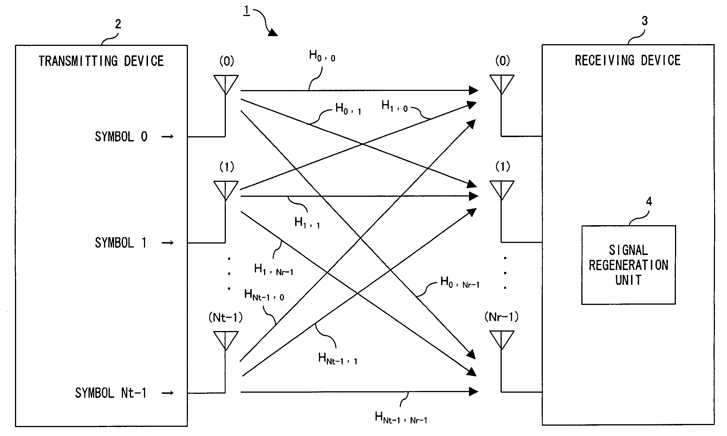
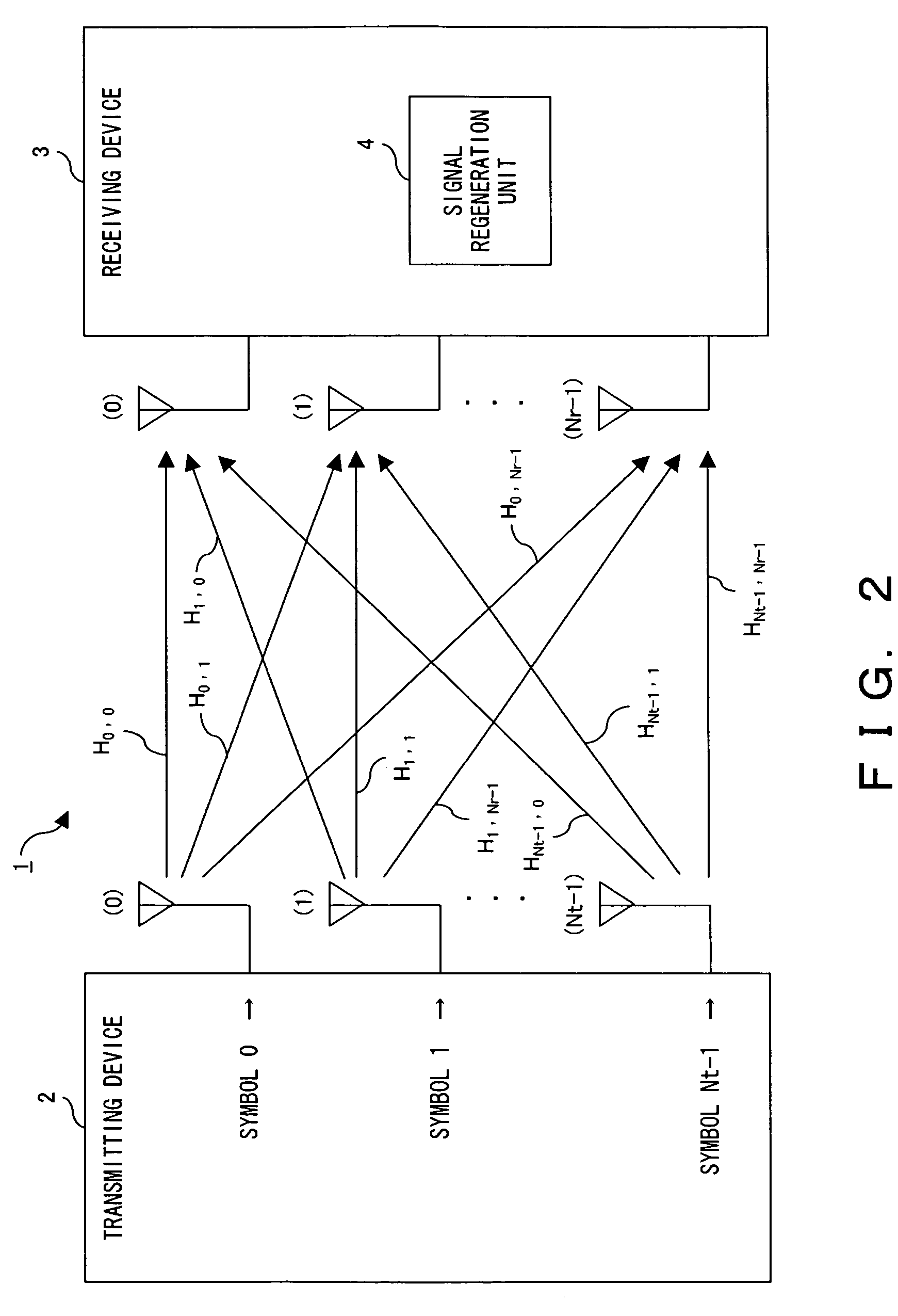
BACKGROUND OF THE INVENTION[0001]1. Field of the Invention[0002]The present invention relates to a system which performs radio communication utilizing a plurality of antennas. In particular, the present invention relates to a technology which compensates channels of a MIMO system in the receiver.[0003]2. Description of the Related Art[0004]MIMO (Multi Input Multi Output) is known as a technology for realizing high-speed radio communication. MIMO is one of the space division multiplex communication systems, and is technology wherein a receiving device and a transmitting device are each provided with a plurality of antennas, and a plurality of radio waves, separated by space, are transmitted in parallel with each other. Here, the plurality of radio waves transmitted from the plurality of the antennas generally have the identical frequency to increase frequency utilization efficiency.[0005]FIG. 1 is a basic configuration diagram of the MIMO system. In FIG. 1, the transmitting device tr...

Claims


Application Information

Patent Timeline
Patent Type & Authority Patents(United States)
IPC IPC(8): H04B7/02H04J99/00H04L25/03H04L27/26
CPCH04L25/03057H04L25/03197H04L25/03292H04L25/03324H04L27/2647H04L1/06
Inventor BOCQUET, WLADIMIR
Owner FUJITSU LTD
Learn More