Light sensor located above an integrated circuit

a technology of integrated circuits and light sensors, applied in the field of microelectronics, can solve the problems of low performance, low efficiency, and loss of parts of the structure, and achieve the effect of minimising dark current and optimal electric qualities

Inactive Publication Date: 2009-02-17
STMICROELECTRONICS SRL
View PDF7 Cites 4 Cited by
  • Summary
  • Abstract
  • Description
  • Claims
  • Application Information

AI Technical Summary

Benefits of technology

[0009]An object of the present invention is to provide a light sensor integrable above an integrated circuit and exhibiting optimal electric qualities, that is, both a chromatic response substantially similar to that of the human eye and a minimum dark current.
[0011]Another object of the present invention is to provide such a light sensor exhibiting a high density of light-emitting diodes of minimum size and comprising color filters which are easy to form.

Problems solved by technology

Such an architecture is expensive since the surface area taken up in the silicon is the sum of the surface areas of the light-emitting diodes and of the MOS transistors.
It has a low performance since not all the light reaches the light-emitting diodes and part of it is lost between the light-emitting diodes.
The light hitting the light-emitting diodes is likely to diffuse and to disturb the operation of the MOS transistors adjacent to the light-emitting diodes.
However, up to now, such architectures result in low performance for the light sensor, in particular in low light.
The sensitivity of the sensor for low lighting levels is low.

Method used


Image

  • Light sensor located above an integrated circuit
  • Light sensor located above an integrated circuit
  • Light sensor located above an integrated circuit

Examples


Embodiment Construction

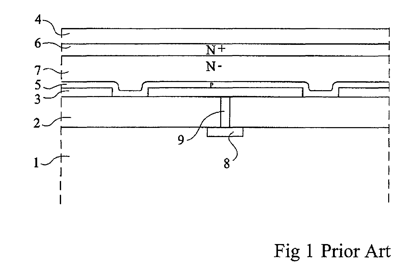
[0028]As usual in the representation of integrated circuits, the scales are not respected in the different cross-section views to better show the different layers and elements of the devices.

[0029]In an attempt to simplify the prior art structure illustrated in FIG. 1, the applicant has formed the structures shown in FIG. 2. FIG. 2 describes an integrated circuit formed in a substrate 1. An insulating layer 2, comprising metal interconnects, is formed above the circuit. Above insulating layer 2 are formed the light-emitting diodes. The light-emitting diodes comprise a lower electrode 10 formed of a titanium nitride layer (TiN) entirely covered with a chromium layer 11 and an upper indium and tin oxide (ITO) electrode 12. The upper electrode is in electric contact with an underlying P-type doped amorphous silicon 13. Between electrode 11 and the P-doped amorphous silicon layer, a lightly-doped N-type amorphous silicon layer 14 has been formed. Thus, the structure of FIG. 2 likely to ...


PUM


Abstract

A light sensor located above an integrated circuit including a lower electrode, a heavily-doped amorphous silicon layer of a first conductivity type, and a lightly-doped amorphous silicon layer of a second conductivity type. The lightly-doped amorphous silicon layer rests on a planar surface at least above and in the vicinity of the lower electrode.

Description

BACKGROUND OF THE INVENTION[0001]1. Field of the Invention[0002]The present invention relates to the field of micro-electronics and more specifically to light sensors associated with an integrated circuit.[0003]2. Discussion of the Related Art[0004]Light sensors are devices which enable turning light signal into an electric signal. Several millions of these sensors can be distributed on a surface to create an electric image comprising millions of points. Usually, a sensor is formed of a light-emitting diode and of a MOS circuit enabling collecting and processing the electric signal issued by the light-emitting diode.[0005]The light-emitting diode may be formed of single-crystal silicon. In this case, the MOS circuit and the light-emitting diode coexist in a single-crystal silicon substrate and are located substantially in the same plane. The MOS transistors which enable collection of the electric current of the light-emitting diodes are located between the light-emitting diodes. Suc...

Claims


Application Information

Patent Timeline
Patent Type & Authority Patents(United States)
IPC IPC(8): H01L31/00
CPCH01L27/1463H01L27/14692H01L31/022408H01L31/103
Inventor THOMAS, DANIELLERIVOIRE, MAURICE
Owner STMICROELECTRONICS SRL
Why Eureka
Try Eureka