Tamperhead for use in production of molded products

a technology for molded products and tamperheads, which is applied in the direction of dough shaping, application, manufacturing tools, etc., can solve the problems of single material manufacturing of tamperheads, avoid adverse effects of welding induced stresses, and reduce the cost of machining metal components. , the effect of high precision

Active Publication Date: 2009-02-17
RAMPF MOLDS INDS
View PDF19 Cites 2 Cited by
  • Summary
  • Abstract
  • Description
  • Claims
  • Application Information

AI Technical Summary

Benefits of technology

[0018]Additionally, construction of the tamperhead structure of the present invention may be simpler and less costly than the traditional tamperhead structures. Non-metal components may be chemically bonded to metal components, avoiding the adverse effects of welding induced stresses. Additionally, plastic parts may be molded with high precision and in large quantities, significantly reducing the cost of machining metal components within tight tolerances. Further, the stresses and warping that accompanies welding are eliminated where adhesive is used to assemble different components of the tamperhead because there is no need to heat the components.
[0019]Furthermore, the use of non-metal material for the plungers may result in significantly more flexibility than traditional steel plungers. The added flexibility of the plungers may reduce the transmission of destructive vibrations from the stripper shoes to the upper head structure. The flexibility may also reduce impact forces experienced by the stripper shoes and the entire tamperhead structure during alignment. The reduction of vibration transmission and the reduction of impact forces work to prolong the usable life of the tamperhead structure and reduce the production cost and machinery repair time.
[0020]Finally, the tamperhead structure of the present invention may weigh less than traditional structures and requires less effort and expense to operate. With the composite tamperhead structure of the present invention, less vibration force may be required to compact the concrete in the molds because the entire production assembly will be lighter and, therefore, easier to vibrate. Also, due to the lighter weight of the tamperhead structure, the production machinery may operate on less power and an operator may experience greater control over the machinery.

Problems solved by technology

First, the tamperhead is not manufactured from a single material.

Method used


Image

  • Tamperhead for use in production of molded products
  • Tamperhead for use in production of molded products
  • Tamperhead for use in production of molded products

Examples


Embodiment Construction

[0031]The present disclosure will now be described more fully with reference to the Figures in which various embodiments of the present invention are shown. The subject matter of this disclosure may, however, be embodied in many different forms and should not be construed as being limited to the embodiments set forth herein.

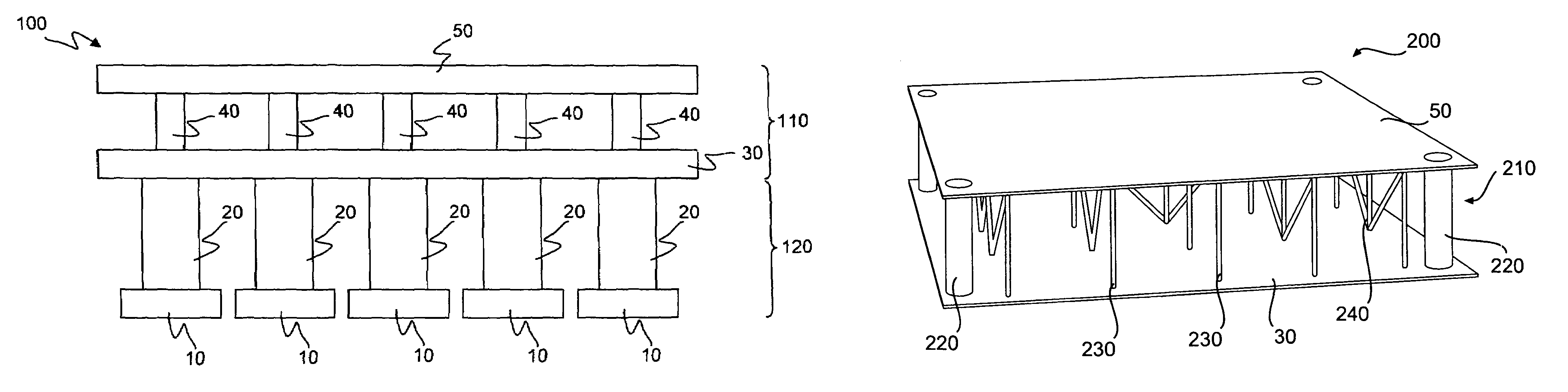
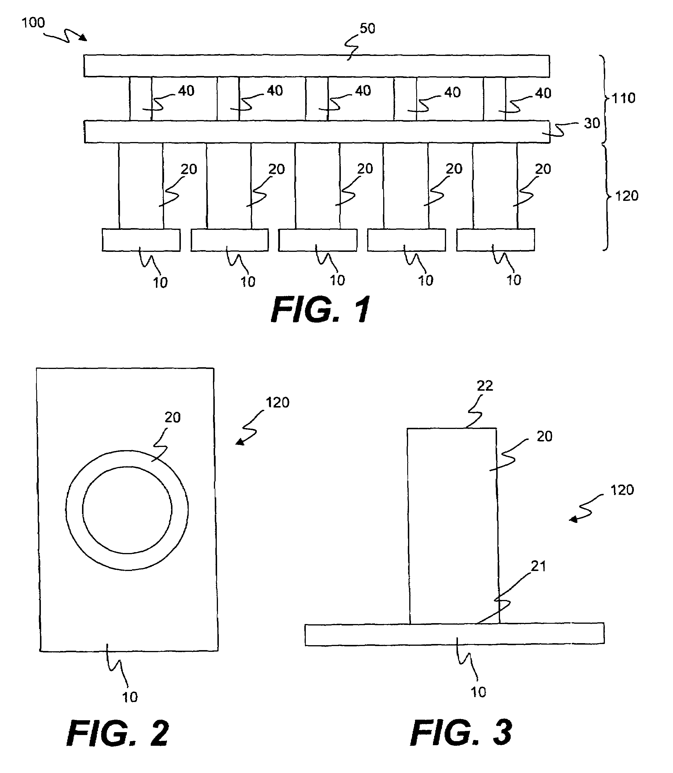
[0032]FIG. 1 shows a front view of a tamperhead structure 100 according to one embodiment of the present invention. The tamperhead structure 100 may include an upper head structure 110 and a lower head structure 120. The lower head structure may include one or more stripper shoes 10 attached to one or more plungers 20. The upper head structure 110 may include a lower plate 30 and an upper plate 50 connected by one or more spacers 40. The shape and thickness of the upper plate 50 and the lower plate 30, and the overall shape and size of the tamperhead structure 100, may vary depending on the production machinery with which it is to be used. While a rectangular sha...


PUM

PropertyMeasurementUnit
weightaaaaaaaaaa
forcesaaaaaaaaaa
structureaaaaaaaaaa

Abstract

The present invention relates to a tamperhead structure including metal and / or non-metal components. The structure may include a top plate and a bottom plate separated by a plurality of spacers. The head structure may also include a plurality of plungers attached to the bottom plate and a stripper shoe attached to each of the plurality of plungers. Each of the components of the tamperhead structure may be fabricated from metal material, non-metal material or a combination of both metal and non-metal materials.

Description

RELATED U.S. APPLICATIONS[0001]This application claims the benefit of U.S. provisional application No. 60 / 690,835 filed Jun. 16, 2005 and entitled “Apparatus and Method for a Composite Head Structure,” incorporated herein by reference.FIELD OF THE INVENTION[0002]The invention generally relates to concrete-based product making machinery. More particularly, the invention relates to a tamperhead for use in machinery for producing molded concrete-based products.BACKGROUND OF THE INVENTION[0003]Concrete masonry units are typically produced using a production machine and a mold assembly. Generally, the mold assembly includes a mold having mold cavities and a tamperhead. The production machinery may drive the tamperhead into the mold to strip formed and compacted concrete products from the mold cavities.[0004]The tamperhead is usually composed of several sub-components which may include an upper head structure, a plunger and a stripper shoe. Multiple sets of stripper shoes and plungers are...

Claims


Application Information

Patent Timeline
Patent Type & Authority Patents(United States)
IPC IPC(8): B28B7/34
CPCB28B1/081B28B3/021B28B3/06
Inventor ISHLER, VINCENT
Owner RAMPF MOLDS INDS
Why Eureka
Try Eureka