
System for distributed programmable control

a programmable control and distributed technology, applied in the field of industrial automation, can solve the problems of inability to achieve the type of information available on demand, and the crude interface used to present the information on the monitoring computer, etc., and achieve the effect of facilitating a complete window into the operation

Inactive Publication Date: 2009-02-10
SCHNEIDER AUTOMATION INC
View PDF43 Cites 8 Cited by
  • Summary
  • Abstract
  • Description
  • Claims
  • Application Information

AI Technical Summary

Benefits of technology

This approach allows for comprehensive, flexible, and cost-effective monitoring and maintenance of industrial equipment, enabling remote personnel to access and visualize controller data, perform diagnostics, and maintain equipment efficiently across distributed sites without the need for extensive graphical capabilities on monitoring computers.

Problems solved by technology

The enormous complexity of ensuring proper task sequencing and management, which requires not only procedural logic but constant monitoring of equipment states to organize and distribute operations and detect malfunction, has resulted in the widespread adoption of programmable controllers.
Control requirements become even more complex when different aspects of the same overall process are assigned to remotely situated equipment.
Heretofore, however, the type of information obtainable, on demand, from a controller has been limited, while the interface used to present the information on the monitoring computer is typically crude.
Not only does this scheme impose a substantial real-time support burden on the monitoring computer, but would also requite a constantly expanding repertoire of graphical capabilities keyed to new forms of data reported by the controllers.
This can be especially cumbersome in highly—even internationally—distributed environments, since the controllers and their functionalities may be programmed by personnel having no contact with those responsible for central monitoring.

Method used


Image

  • System for distributed programmable control
  • System for distributed programmable control
  • System for distributed programmable control

Examples


Embodiment Construction

Brief Summary of the Invention

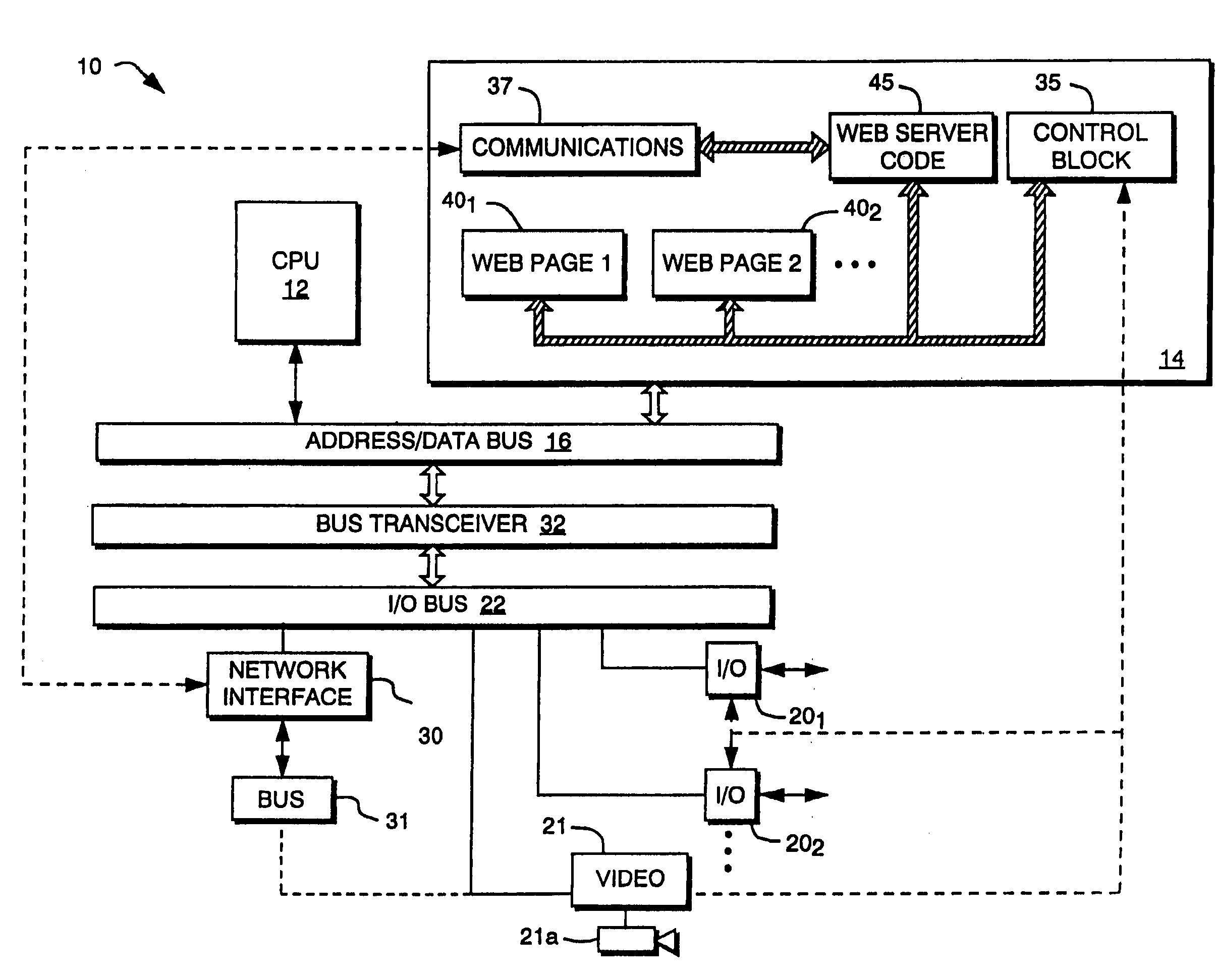
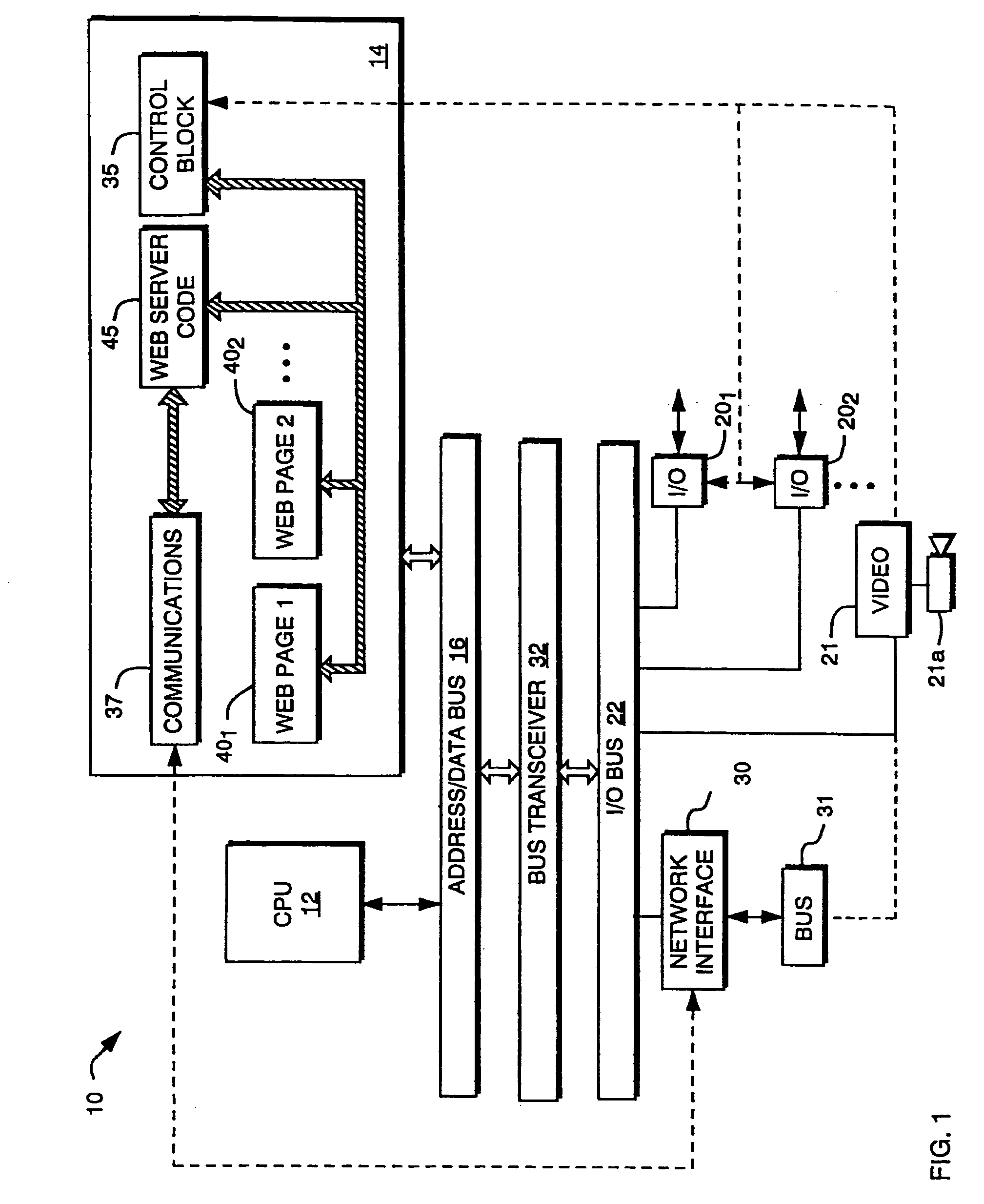
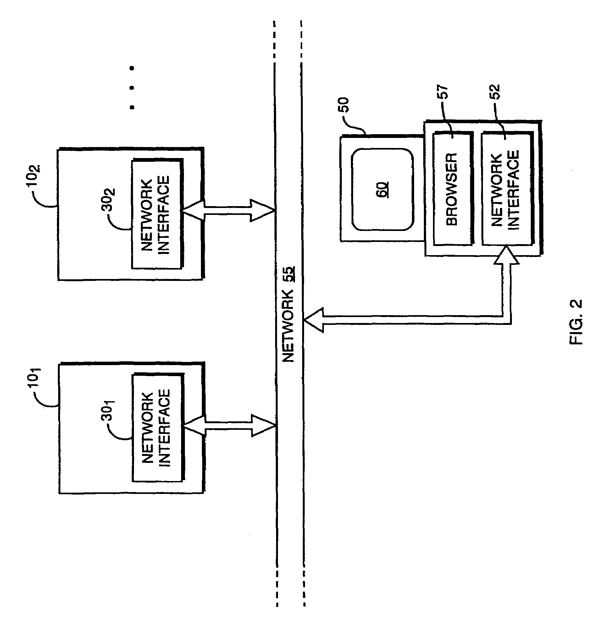
[0008]The present invention utilizes the capabilities of the Internet and, more particularly, the interactive capabilities made available by resources such as the World Wide Web to shift the burden of providing user interfaces for changing forms of data from monitoring computers to the controllers that actually gather and report the data. By combining data with functionality for displaying that data at the individual controller sites, the need to equip monitoring computers with specialized graphic capabilities is eliminated, along with the need for intensive, ongoing cooperation between engineers responsible for programming controllers and those who configure the computers that perform monitoring. Moreover, because Internet users are typically billed for connectivity at a single rate, the long-distance charges that would accrue through use of telephone lines for data communication are eliminated.

[0009]In accordance with the invention, an integrated cont...


PUM


Abstract

An integrated control system comprises one or more controllers each equipped to perform a control function and to gather data (ordinarily from sensors) relevant to the control function. The data is combined with instructions, associated with the data, for causing a remote computer to generate a visual display incorporating the data in a predetermined format. A communication module establishes contact and facilitates data interchange with the remote computer over the World Wide Web.

Description

CROSS-REFERENCE TO RELATED APPLICATION[0001]This Application is a continuation of U.S. patent application Ser. No. 09 / 436,368, filed on Nov. 8, 1999, now U.S. Pat. No. 7,146,408 entitled “DISTRIBUTED INTRFACE ARCHITECTURE FOR PROGRAMMABLE IDUSTRIAL CONTROL”, which is a continuation claiming benefit to, U.S. patent application Ser. No. 08 / 851,664, filed May 6, 1997 now U.S. Pat. No. 5,775,305, which is itself a continuation-in-part of application Ser. No. 08 / 655,469, filed May 30, 1996, now U.S. Pat. No. 5,805,442.FIELD OF THE INVENTION[0002]The present invention relates to industrial automation, and in particular to communication with and among programmable controllers for operating and monitoring industrial processes and equipment.BACKGROUND OF THE INVENTION[0003]Sophisticated industrial processes, such as oil refining, automobile assembly or power generation, require the cooperative execution of numerous interdependent tasks by many different pieces of equipment. The enormous comp...

Claims


Application Information

Patent Timeline
Patent Type & Authority Patents(United States)
IPC IPC(8): G06F13/00F02M49/02G05B19/418G06F9/44
CPCF02M49/02G05B19/4185G05B2219/31156G05B2219/31186G05B2219/31205G05B2219/34038Y02P90/02
Inventor CRATER, KENNETH C.GOLDMAN, CRAIG E.
Owner SCHNEIDER AUTOMATION INC
Learn More