
Resin molded component fitted with a metal plate and molding method therefor

a technology of resin molded components and metal plates, which is applied in the direction of electrical apparatus casings/cabinets/drawers, coupling device connections, instruments, etc., can solve the problems of increasing the number of parts, difficult to fix the connection to the resin molded component, and the fixed position of the busbar is likely to vary, so as to achieve convenient detachable, reliable riveting, and improved position accuracy of the exposed end of the busbar relative to the surface of the metal pla

Active Publication Date: 2009-02-10
SUMITOMO WIRING SYST LTD
View PDF12 Cites 8 Cited by
  • Summary
  • Abstract
  • Description
  • Claims
  • Application Information

AI Technical Summary

Benefits of technology

The invention is a resin molded component that is fit with at least one metal plate. The metal plate is inserted during the molding process of the resin molded component, and an electronic component is held on the surface of the metal plate. The electronic component is held in place by a busbar that is also inserted molded. The positional accuracy of the electronic component is improved by using guiding walls on the metal plate for positioning. The invention provides a reliable and secure connection between the electronic component and the metal plate, and prevents the electronic component from moving during the connection process. The method for molding the resin molded component includes steps for insert-molding a primary molded portion and a secondary molded portion. The invention has improved the mount position of the electronic component and reduced interference between parts, resulting in a more efficient and reliable connection.

Problems solved by technology

However, a riveted connection to a busbar fixed to a resin molded component is not easy.
However, the fixed position of the busbar is likely to vary due to changes in pressure, temperature and other factors upon squeezing the rib.
The flat cable that is interposed in the above-described solder connection increases the number of parts and the soldering operation adds to the cost.

Method used


Image

  • Resin molded component fitted with a metal plate and molding method therefor
  • Resin molded component fitted with a metal plate and molding method therefor
  • Resin molded component fitted with a metal plate and molding method therefor

Examples


Embodiment Construction

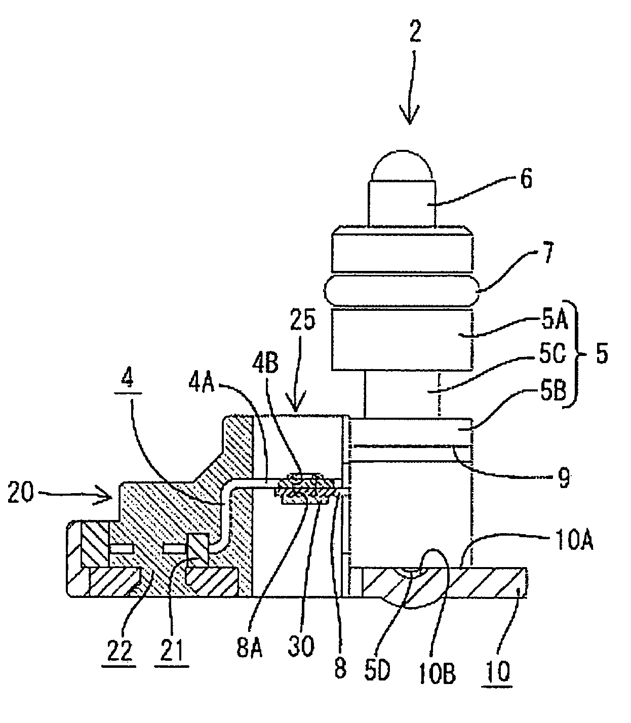
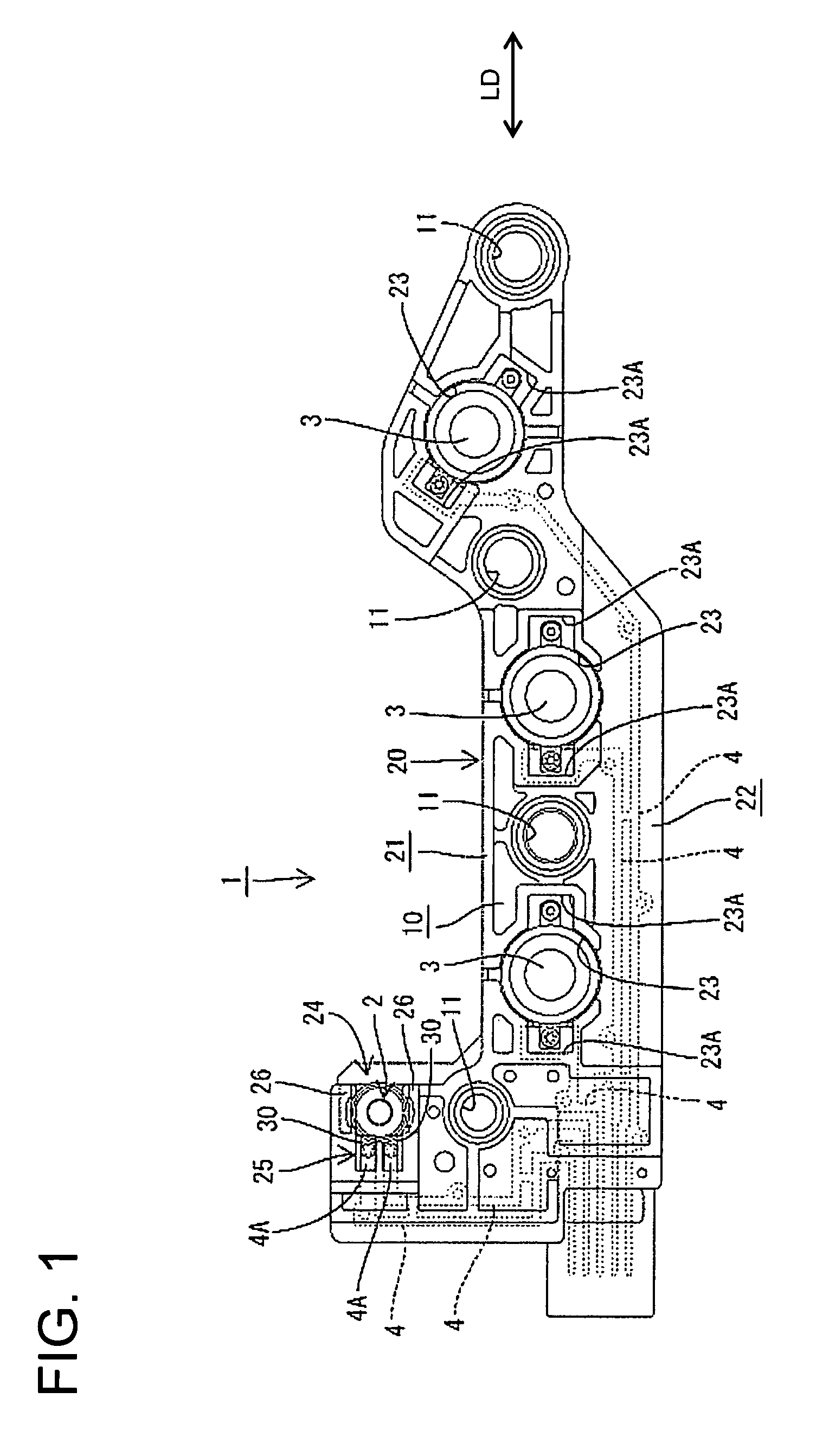
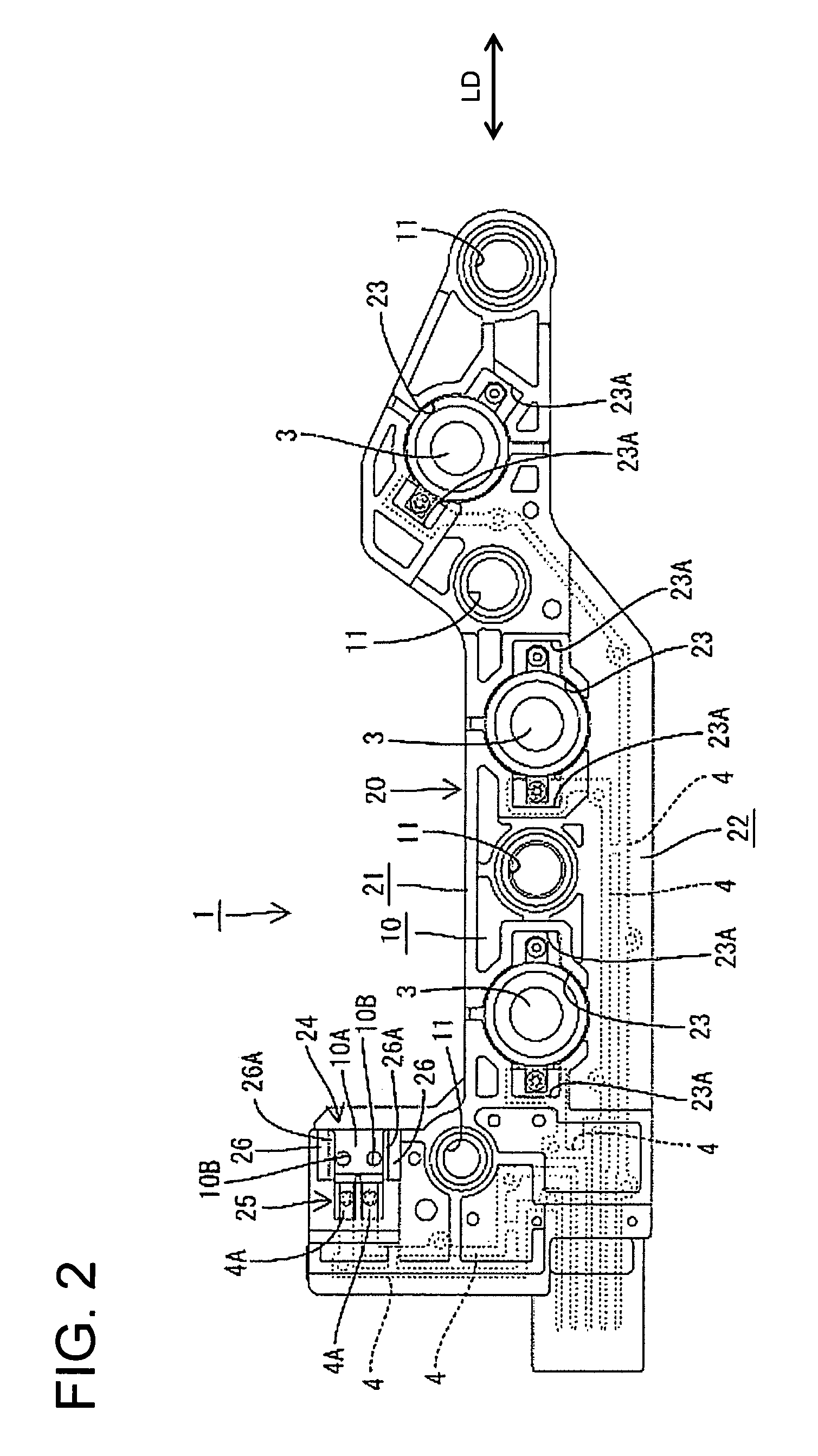
[0024]A sensor unit is identified generally by the numeral 1 in FIGS. 1 to 4, and is described herein as an example of a resin molded component fit with a metal plate. The sensor unit 1 is to be mounted in an automotive transmission, and sometimes comes into contact transmission oil or other fluid. The sensor unit 1 is provided with at least one metal plate 10, a resin molded portion 20 insert-molded to be integral to the metal plate 10, and electronic components that include an oil temperature sensor 2 and oil pressure sensors 3. The resin molded portion 20 is made e.g. of a synthetic resin or a synthetic resin containing a reinforcement (e.g. 6,6 nylon containing glass fibers). Metal busbars 4 are arranged at least partly in the resin molded portion 20. The resin molded portion 20 includes a primary molded portion 21 insert-molded to be integral to the metal plate 10 at a surface of the metal plate 10 shown in FIG. 1, and a secondary molded portion 22 insert-molded to be integral ...


PUM

PropertyMeasurementUnit
temperatureaaaaaaaaaa
pressureaaaaaaaaaa
capacitanceaaaaaaaaaa

Abstract

A sensor unit (1) has a metal plate (10), a resin molded portion (20) and an oil temperature sensor (2). Busbars (4) made of a metal are arranged in the resin molded portion (20). Since the busbars (4) are insert-molded while having the exposed ends (4A) thereof tightly held by a pair of forming dies, a distance between the exposed ends (4A) and the placing surface 10A is held constant. Further, gate marks (5D) of the oil temperature sensor (2) are accommodated in recesses (10B) of the placing surface (10) and engaging grooves (9) and engaging projections (26A) are engaged. Thus, the oil temperature sensor (2) can be held in a proper posture. Additionally, the oil temperature sensor (2) can be held on the placing surface (10A) by riveting the exposed end (4A) and a terminal (8) of the oil temperature sensor (2).

Description

BACKGROUND OF THE INVENTION[0001]1. Field of the Invention[0002]The invention relates to a resin molded component fit with a metal plate and to a molding method therefor.[0003]2. Description of the Related Art[0004]The terminal of an electronic component generally is connected to a wiring member by soldering or riveting. However, a riveted connection to a busbar fixed to a resin molded component is not easy. More particularly, to fix a busbar to a resin molded component, a resin rib generally is formed to stand on a base plate. The rib then is inserted through a through hole in the busbar and is squeezed at high temperature. However, the fixed position of the busbar is likely to vary due to changes in pressure, temperature and other factors upon squeezing the rib. If the busbar and the electronic component are connected forcibly by riveting, the mount position of the electronic component is restrained by the position of the busbar. Therefore the electronic component is fixed at a po...

Claims


Application Information

Patent Timeline
Patent Type & Authority Patents(United States)
IPC IPC(8): H01L23/28
CPCB29C45/1671H05K3/202B29C45/14655B29C2045/0027H05K1/056H05K3/326H05K2201/0397H05K2201/09118H05K2201/10151H05K2201/10401H05K2201/10651
Inventor MAEGAWA, AKIHITONAGASHIMA, SHINYU
Owner SUMITOMO WIRING SYST LTD
Learn More