
Retrofitting of fluorescent tubes with light-emitting diode (LED) modules for various signs and lighting applications

a technology of led modules and fluorescent tubes, applied in the direction of lighting support devices, coupling devices, instruments, etc., can solve the problems of difficult retrofitting of led lamps to difficult to replace short-life fluorescent tube lamps in conventional backlit commercial and street signs, and difficult to install without special tools

Active Publication Date: 2009-02-10
LEOTEK ELECTRONICS
View PDF22 Cites 46 Cited by
  • Summary
  • Abstract
  • Description
  • Claims
  • Application Information

AI Technical Summary

Benefits of technology

"The present invention provides a method and apparatus for installing a retrofit LED lamp module in a housing designed for fluorescent tube lamps. This allows for the replacement of traditional fluorescent lamps with LED lamps that offer improved energy efficiency and longer lifespan. The LED lamp module includes an elongated electrical assembly with LEDs mounted thereon, and two mounting adaptors that connect to the housing's sockets. The LED lamp is easily installed by connecting the adaptors to the sockets and powering the LEDs. The technical effects of this invention include improved energy efficiency, longer lifespan, and easy installation."

Problems solved by technology

Retrofitting with LED lamps the vast numbers of backlit commercial and street name signs, which utilize fluorescent lighting, is more problematic.
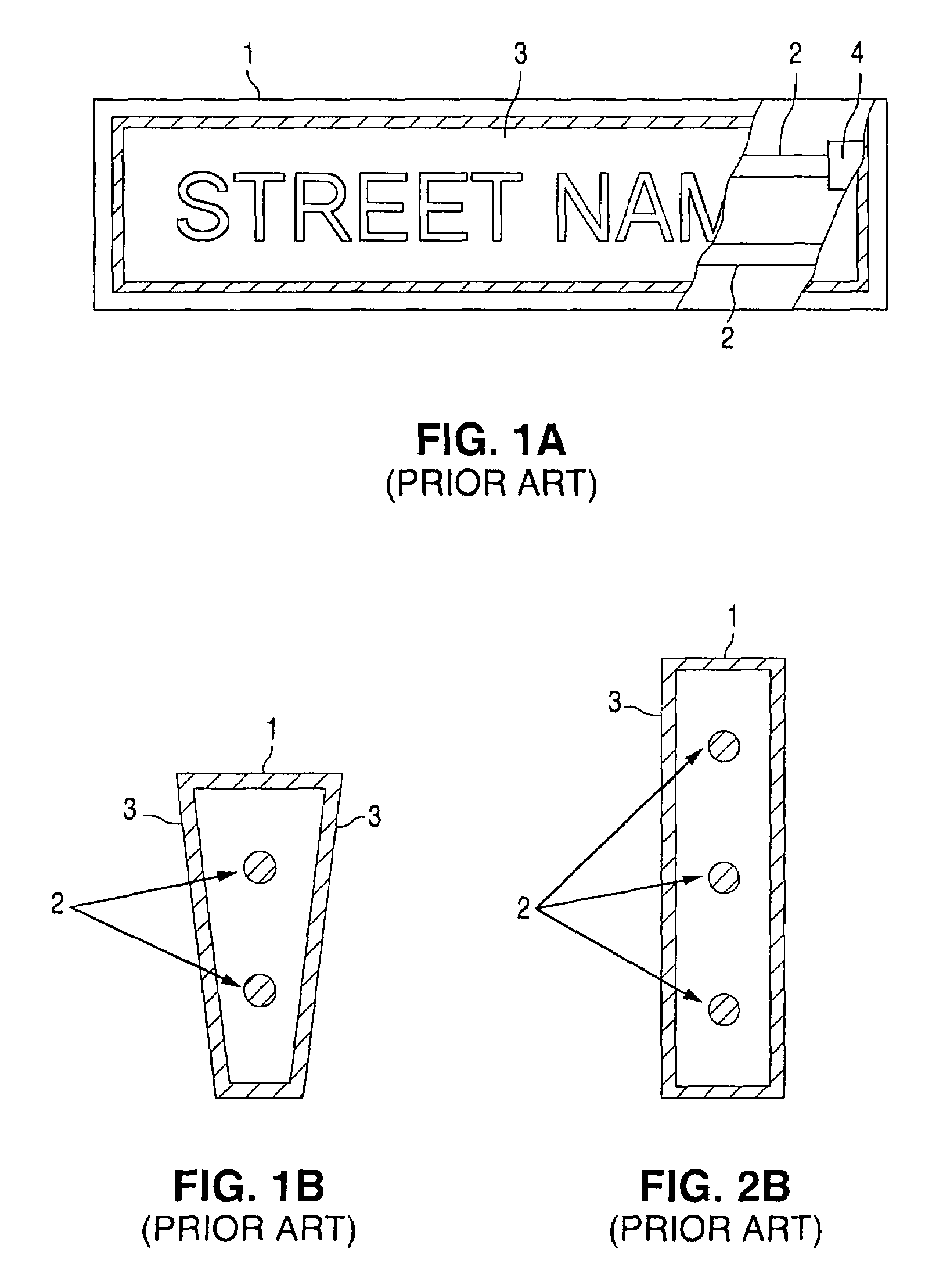
Replacing the short-lifespan fluorescent tube lamps in conventional backlit commercial and street name signs can be difficult, because such signs are typically elevated and inaccessible, disposed over roadways, and / or hard to open.
Thus, designing an LED lamp retrofit that fits a wide variety of such signs, that evenly and sufficiently illuminates such signs, and that is easy to install without the need for special tools, has been difficult.
Adding to that difficulty is the fact that many such signs are suspended in a way where the sign rocks, vibrates and shakes in the wind.

Method used


Image

  • Retrofitting of fluorescent tubes with light-emitting diode (LED) modules for various signs and lighting applications
  • Retrofitting of fluorescent tubes with light-emitting diode (LED) modules for various signs and lighting applications
  • Retrofitting of fluorescent tubes with light-emitting diode (LED) modules for various signs and lighting applications

Examples


Embodiment Construction

[0033]The present invention relates to the design and the installation of retrofit LED modules to replace existing fluorescent tube lamps. Moreover, the present invention provides a method and apparatus for installing a retrofit LED lamp module in a housing designed for fluorescent tube lamps.

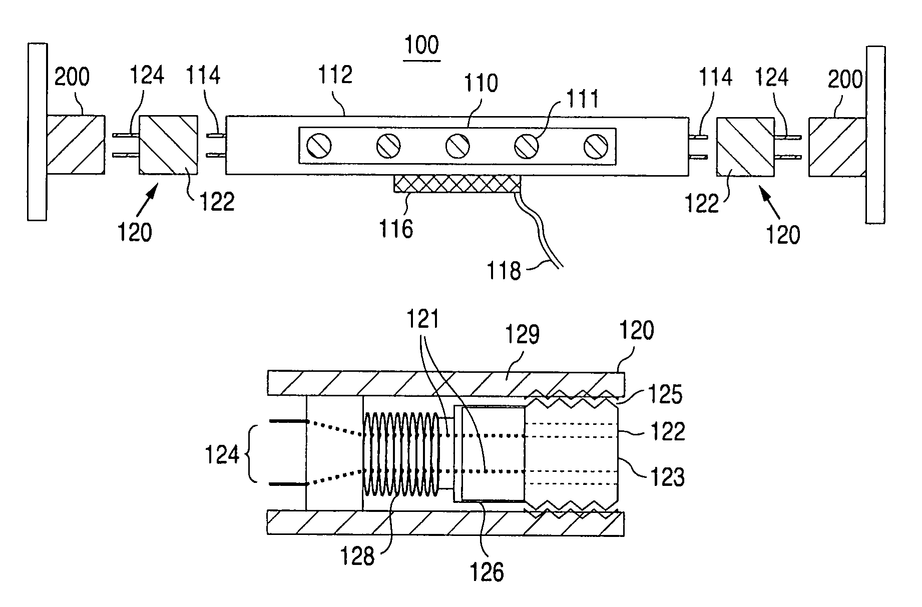
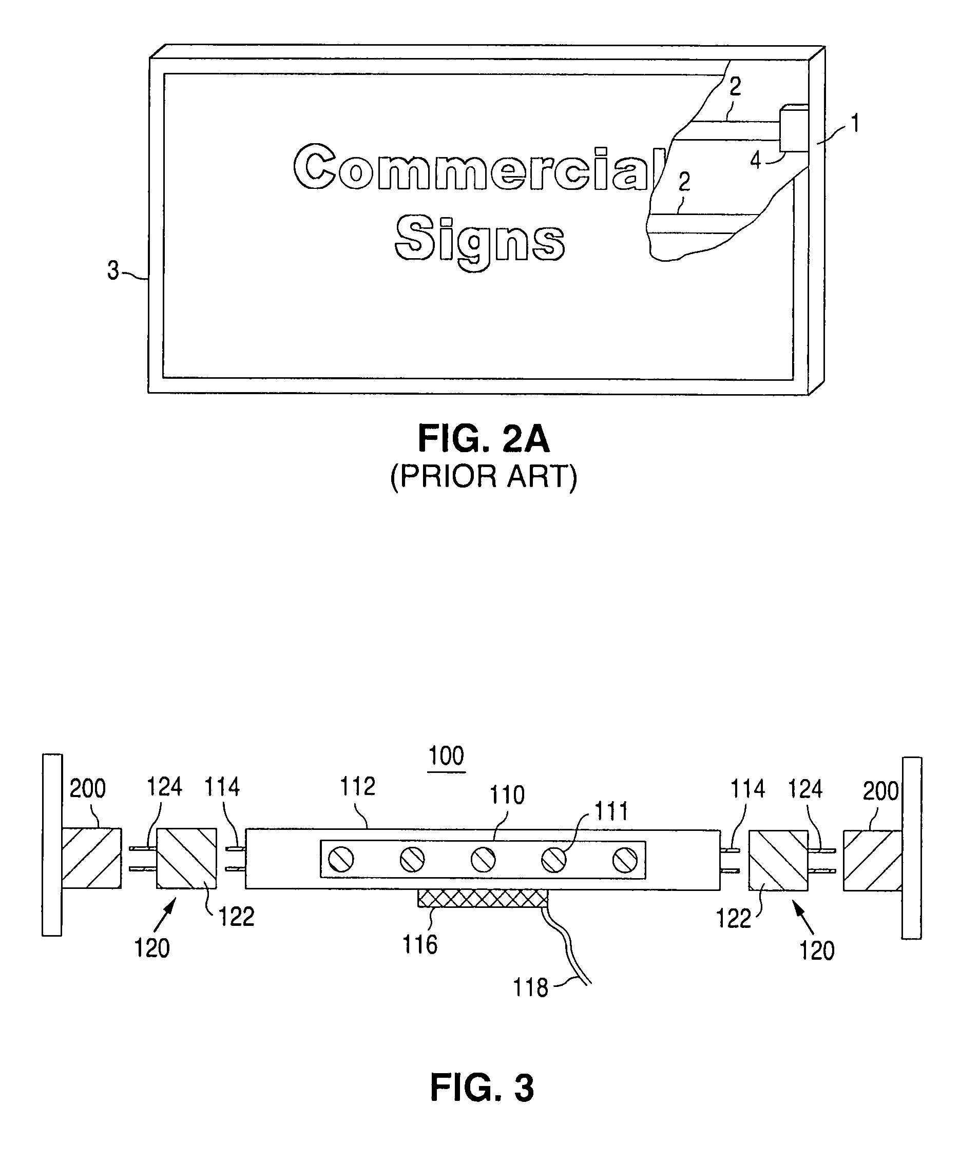
[0034]In FIG. 3, a schematic of an LED module 100 according to an embodiment of the present invention is provided. As illustrated, LED module 100 includes a plurality of LEDs 111 mounted onto an elongated electrical assembly 110 (e.g. a printed circuit board, a plurality of electrical receptacles, etc.), and preferably housed within a translucent LED tube 112. On both ends, LED module 100 includes bi-pin connectors 114, which allow LED module 100 to electrically connect to mounting adaptors 120 via bi-pin holes 122. In a preferred embodiment, each mounting adaptor 120 further comprises bi-pin connectors 124, which allow each adaptor 120 to electrically connect to a conventional fluorescent tube...


PUM


Abstract

A method and device for replacing a fluorescent tube lamp with an LED lamp. The LED lamp includes an elongated electrical assembly having ends terminating in first and second electrical connectors, and a plurality of LEDs mounted to the elongated electrical assembly. Mounting adaptors connect with the first and second electrical connectors, and have protruding pins to connect with conventional lamp socket connectors. The mounting adaptors have rotating connectors for connecting with the first and second electrical connectors of the LED lamp, so that the LED lamp orientation can be rotated after the LED lamp is fully mounted to the lamp socket connectors.

Description

[0001]This application claims the benefit of U.S. Provisional Application No. 60 / 789,673, filed Apr. 5, 2006, and entitled Retrofitting of Fluorescent Tubes with Light-Emitting Diode (LED) Modules for Various Signs and Lighting Applications.FIELD OF THE INVENTION[0002]The present invention relates to the design and the installation of retrofit Light Emitting Diode (LED) modules to replace existing fluorescent tube lamps typically found in street lights, parking lot lights, and various other lighting applications. More particularly, the present invention relates to a method and apparatus for installing a retrofit LED module in a conventional fluorescent tube lamp housing.BACKGROUND OF THE INVENTION[0003]Light emitting diodes (LEDs) have been widely used in many applications to replace conventional incandescent lamps, fluorescent lamps, neon tube lamps and fiber optic lights. LEDs consume much less electrical power, are far more reliable, and exhibit much longer lifetimes, than their ...

Claims


Application Information

Patent Timeline
Patent Type & Authority Patents(United States)
IPC IPC(8): F21S4/00F21V21/00F21V7/04H01R33/00H01R33/02
CPCF21V19/008F21V19/02F21V23/003G09F13/04H01R31/06H01R33/94F21Y2101/02F21Y2103/003F21Y2105/001H01R35/00F21Y2105/10F21Y2103/10F21Y2115/10F21K9/278Y02B20/30
Inventor WU, CHEN-HOTU, CHIN-WANG
Owner LEOTEK ELECTRONICS
Learn More