Acoustic projector and method of manufacture

a technology of acoustic projectors and manufacturing methods, applied in the field of underwater acoustics, can solve the problems of more cost effective and fast assembly methods, and achieve the effects of stiffening the longitudinal assembly, and reducing the number of segments

Active Publication Date: 2009-01-27
BAE SYST INFORMATION & ELECTRONICS SYST INTERGRATION INC
View PDF25 Cites 1 Cited by
  • Summary
  • Abstract
  • Description
  • Claims
  • Application Information

AI Technical Summary

Benefits of technology

[0008]To solve this problem the acoustic projector of the present invention can be assembled in a “super segment” method with multiple drivers as part of a shell segment. This not only stiffens the longitudinal assembly but also reduces the number of segments for interactions to occur. The goal is to reduce the number of segments to 2 segments. If this is not possible then an even number of segments is needed. This solution solves interactions in the slotted cylinder projector, however this technique can be used in other transducer technologies.
[0009]The most significant advantage to the new constructions method is, multiple drivers in one shell segment which stiffens the shell segments in the longitudinal length direction and reduces longitudinal vibrations modes as well as significantly reduces acoustic segment interactions, usually caused by hydrodynamic load variations along the length. The new method and acoustic projector construction is also not constrained by the manufacturable length of the drive material. The shell segment can be any length and multiple drivers can be assembled inside one shell segment. Additionally, this method is more cost effective and faster to assemble due to the reduced number of parts and pieces that need to be purchased or handled. Also the designer can use this construction method to ensure that the projector is designed with one or two shell segments, which is the optimum segment number(s) to eliminate segment interactions. If one or two segments can't be used then the designer has the flexibility to ensure an even number of shell segments can be used and any interactions can be managed via wiring, tuning, or shading methods.

Problems solved by technology

Additionally, this method is more cost effective and faster to assemble due to the reduced number of parts and pieces that need to be purchased or handled.

Method used


Image

  • Acoustic projector and method of manufacture
  • Acoustic projector and method of manufacture
  • Acoustic projector and method of manufacture

Examples


first embodiment

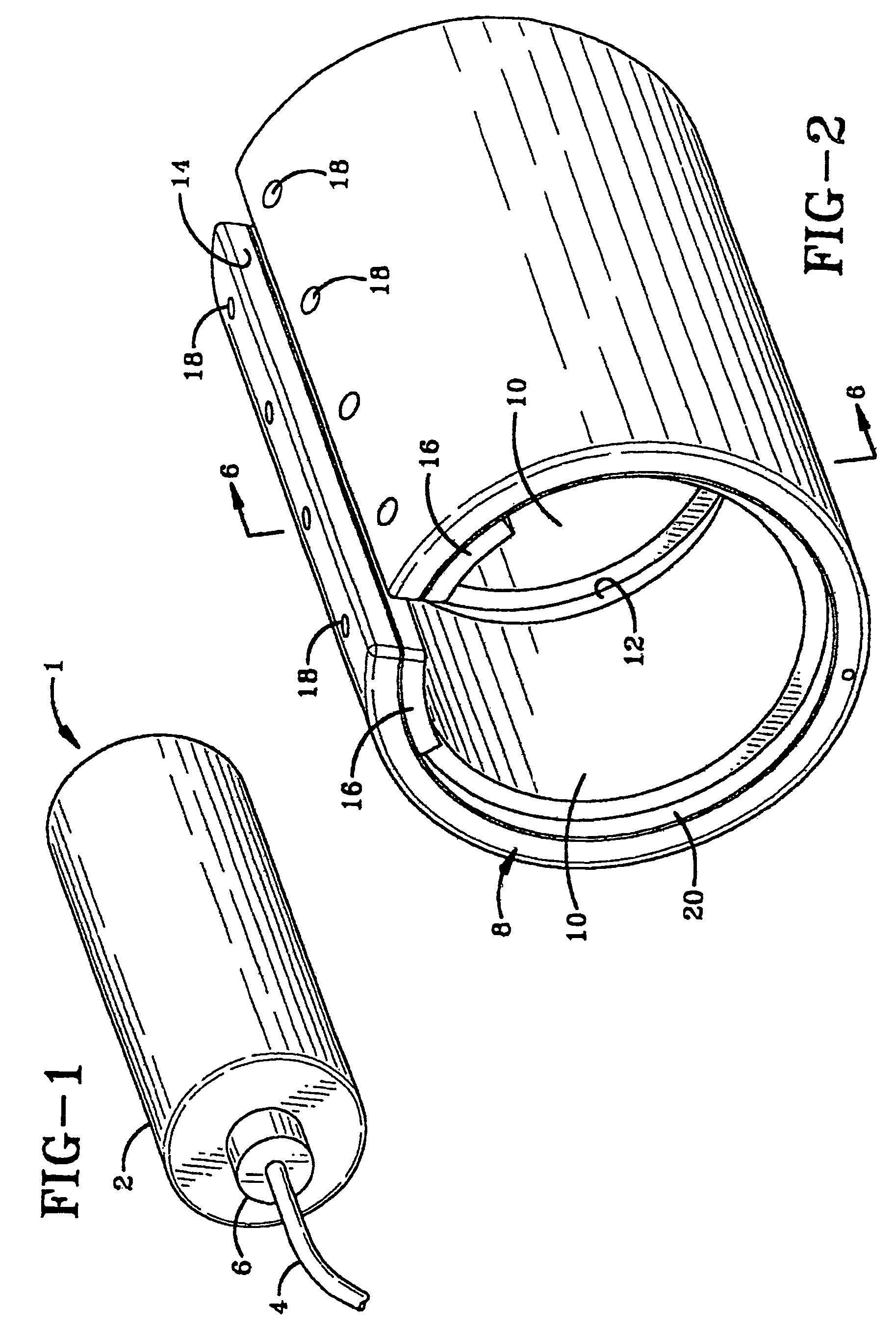
[0020]The acoustic projector of the present invention is indicated generally at 1, and a first embodiment is shown in FIG. 1 with the unique features of the present invention being shown particularly in the embodiments of FIGS. 2 and 3. FIG. 1 shows an assembled acoustic projector having the assembled shell segments and drivers encased in an outer layer of a rubberized material 2 or other material resistant to the harsh undersea environment in which it will be utilized. The electrical cables 4 for supplying power to the enclosed drivers are secured by a connection 6. The electrical power is connected to the drivers contained therein in a usual manner well known in the acoustic projector art. It is readily understood that projector 1, in addition to the unique shell segments described below, will have a pair of end plates (not shown) connected together in the final projector assembly.

[0021]In accordance with the invention as shown in FIG. 2, a single shell segment 8 contains two tran...

embodiment 22

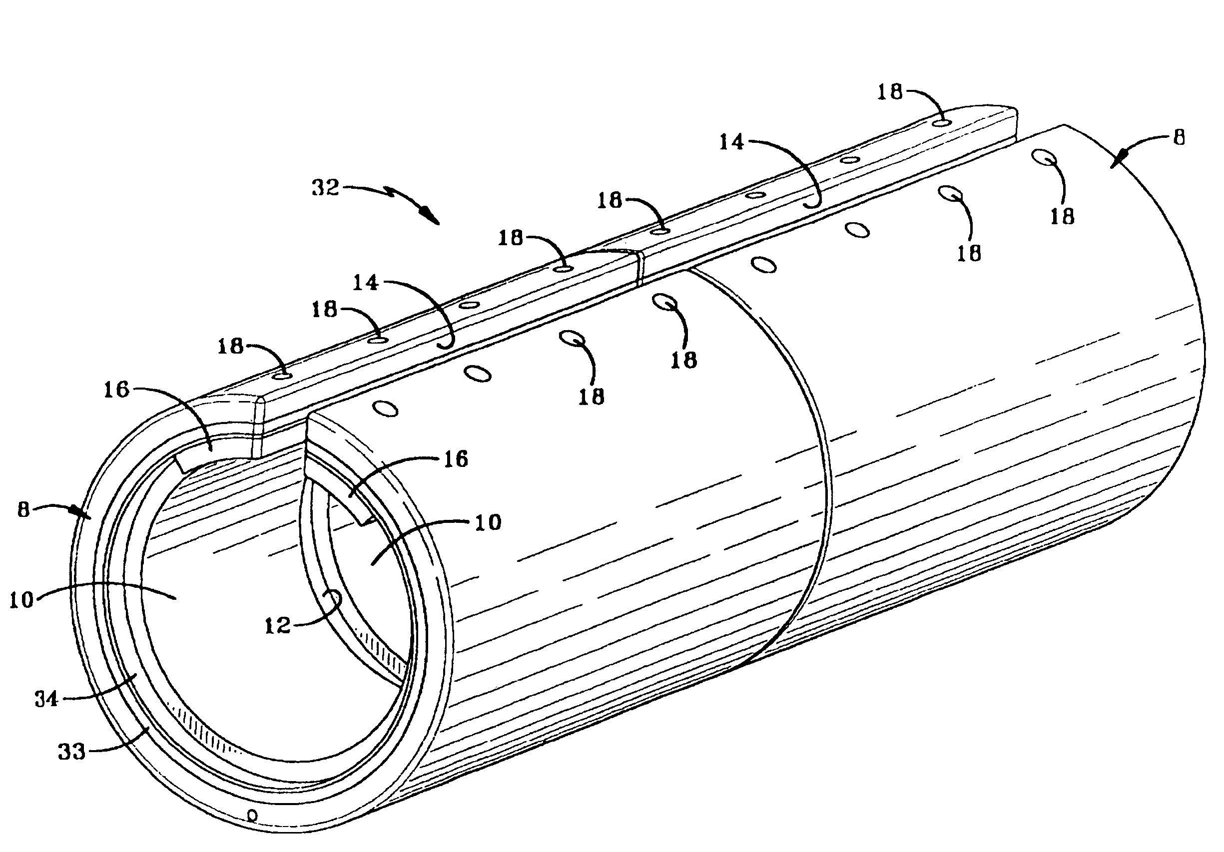
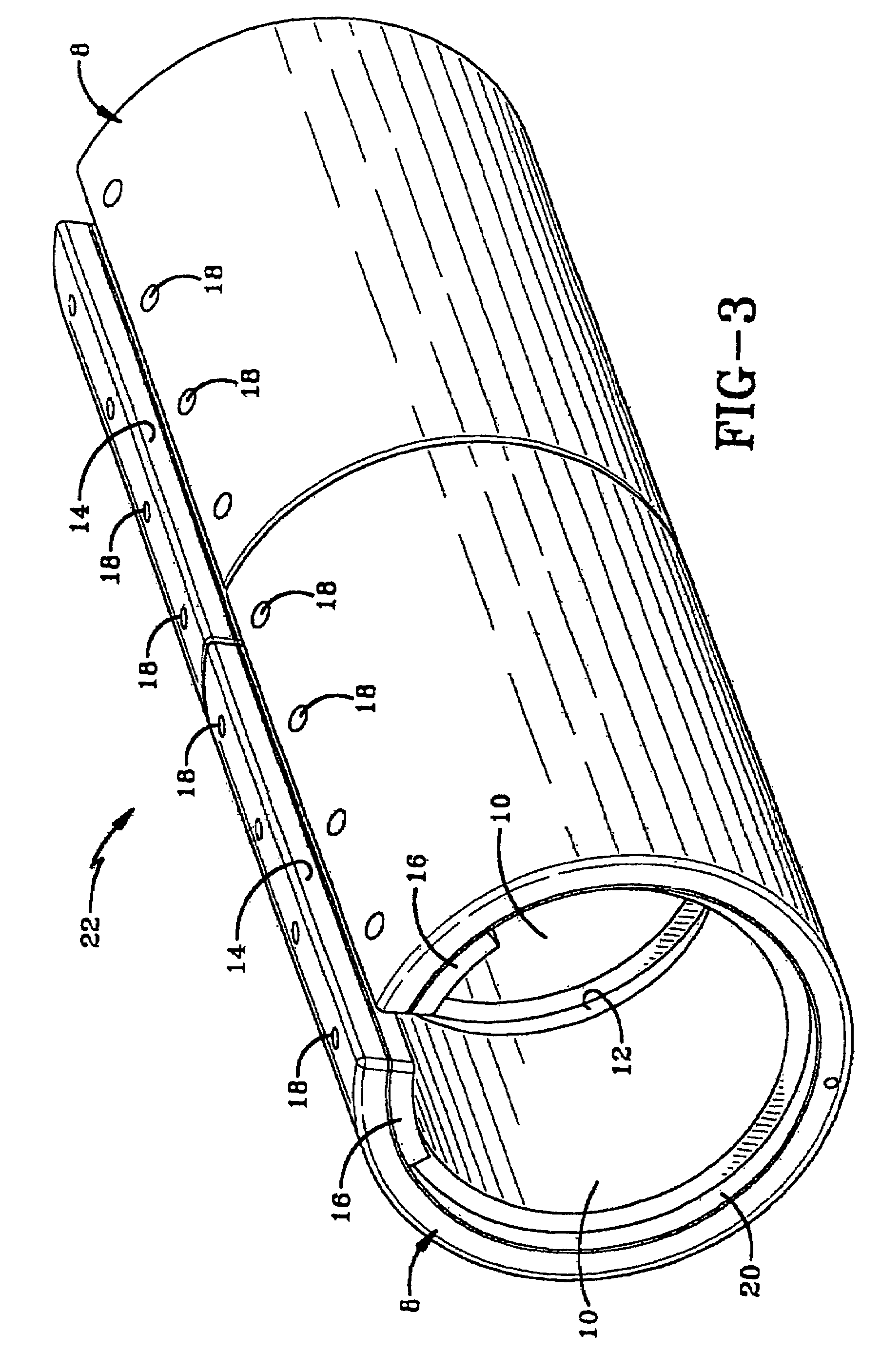
[0024]A modified form or extension of the present invention is indicated generally at 22, and shown in FIG. 3. Embodiment 22 consists of a pair of shell segments 8, and as discussed above, each segment 8 containing a pair of drivers 10, which segments are joined together to provide a multiple shell segment, each containing multiple drivers. The remaining construction of projector 22 is similar to that described with respect to shell 8 and driver 10. The shell segments preferably are longitudinally joined by a lower alignment pin 24 (FIG. 4) with various types of epoxies or glues at their mating edges.

[0025]It is also understood that other multiple shell segments can be joined longitudinally, each containing multiple drivers, for example, four shell segments could be joined, six shell segments, etc. It is preferable that the number of shell segments be even multiples of two, and as discussed above, the number of drivers being multiples of two in each of the shell segments. This arran...


PUM


Abstract

An underwater acoustic projector comprising one or more cylindrical shell segments (8), each shell segment (8) having an even number of drivers (10) mounted therein, and the method of manufacturing said projector. The shell segments (8) preferably are formed with a longitudinal slot (14) and have arcuate segments (16), preferably of a dielectric material extending along the sides of the slot (14) for retaining the drivers (10) within the shell segments (8). The combined lengths of the driver is between 70% and 90% of the shell segment (8) length.

Description

CROSS REFERENCE TO RELATED APPLICATION[0001]This application claims the benefit of U.S. provisional application Ser. No. 60 / 529,445, filed Dec. 12, 2003.BACKGROUND OF THE INVENTION[0002]1. Field of the Invention[0003]The present invention relates to underwater acoustics and more particularly to underwater acoustic projectors and to the method of manufacturing the same. More particularly, the invention relates to an acoustic projector formed of one or more shell segments wherein each shell segment has an even number of drivers.[0004]2. Brief Description of Prior Developments[0005]In low frequency underwater acoustic projectors, a segmented assembly is used to ease piece part manufacturability, assembly and handling procedures. However this assembly procedure can result in acoustic segment interactions due to a longitudinal vibration mode and / or interaction due to water loading differences along the length of the projector. Segment interactions can disrupt and distort the acoustic tra...

Claims


Application Information

Patent Timeline
Patent Type & Authority Patents(United States)
IPC IPC(8): H04R17/00G10K11/00B06B1/06H01L41/08H04R31/00
CPCB06B1/0633H04R1/24H04R1/2888
Inventor DEANGELIS, MATTHEW M.OSBORN, JASON W.
Owner BAE SYST INFORMATION & ELECTRONICS SYST INTERGRATION INC
Why Eureka
Try Eureka