
Battery powered LED lamp

a battery-powered led lamp technology, applied in the field of electronic lighting devices, can solve the problems of low light level for the amount of power consumed, relatively low energy utilization efficiency, and inability to provide a lighting source for such venues, and achieve the effect of reducing overall efficiency, reducing light brightness, and maximum brightness

Inactive Publication Date: 2009-01-27
ANDERSON GARY
View PDF15 Cites 29 Cited by
  • Summary
  • Abstract
  • Description
  • Claims
  • Application Information

AI Technical Summary

Benefits of technology

[0012]The converting electronics may also include an LED current monitoring circuit for preventing thermal runaway of the LEDs. This circuit reduces the voltage applied to the LEDs as the LED's temperature rises, thereby reaching a stable condition. The current monitoring circuit may include a low valued current sensing resistor in series with the LEDs, forming a feedback loop to the threshold voltage input pin of the switching regulator.
[0013]A benefit of the current monitor circuit incorporated in the converting electronics of embodiments of the invention is to reliably operate the LEDs near their maximum rating so to provide the maximum amount of brightness from the LED array. Simple provisions via a potentiometer arrangement within the current monitoring circuit provide a user adjustable LED light dimming capability without a reduction in overall efficiency. For a battery power source, reducing the light brightness yields longer operating times due to lower battery energy consumption.
[0014]An advantage of embodiments of the invention is that a relatively constant light output level is maintained throughout the life of the batteries. In some embodiments, from 9 to 45 hours of operation may be achieved before any dimming of the light output is encountered or the batteries are depleted.
[0015]In other embodiments of the invention, a battery charging circuit is incorporated in a housing and attachment clip assembly. A lithium-ion or other high performance battery may be also enclosed in the housing. The battery charging circuit may include digital logic enabling rapid and safe charging of the battery.

Problems solved by technology

Further, it is sometimes desirable to read books and consult printed materials in locations where ambient lighting is insufficient for comfortable reading, as for example, at night in an automobile.
Prior attempts at providing a lighting source for such venues have not been entirely successful.
Incandescent sources, while being relatively inexpensive, also have the drawback of relatively low energy utilization efficiency.
This low efficiency results in low light level for amount of power consumed, as well as excessive heat production in the bulb.
For battery powered devices, batteries are quickly depleted requiring frequent replacement for alkaline batteries, and frequent recharging for rechargeable type batteries.
Moreover, AC power lamps have the drawback of requiring a nearby AC power source.
An AC power source is often not readily available in locations where a lamp is desirably used, for example in automobiles.
Also, a bulky power cord sometimes including a transformer is required.
Further, incandescent bulbs have a relative short service life and require frequent replacement.
A drawback, however, is the generally bulky and relatively heavy ballast required for fluorescent bulbs.
Also, while having a much longer life than incandescent bulbs, fluorescent bulbs contain mercury and other harmful substances, requiring specialized disposal when the bulb is replaced.
Prior compact LED lamps, however, have generally suffered from a number of drawbacks.
In these devices, the light is usually of poor quality even with fully charged batteries, and has poor overall color and temperature characteristics.
The quality of light from these devices degrades quickly as the batteries are discharged.
Just as significant is the poor overall energy consumption efficency of prior simple LED driving circuits.
As a result of the low efficiency of prior LED lamps, frequent battery replacement or recharging is required in battery powered devices to maintain an acceptable light level.
AC powered LED lamp devices have been developed which alleviate the problems with battery usage, but these devices suffer from many of the same deficiencies as AC powered incandescent devices.

Method used


Image

  • Battery powered LED lamp
  • Battery powered LED lamp
  • Battery powered LED lamp

Examples


Embodiment Construction

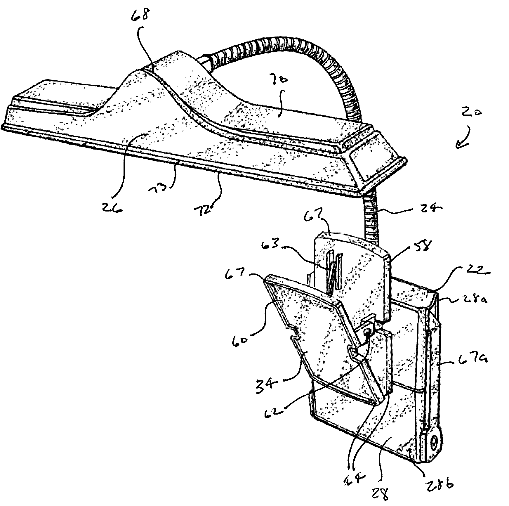
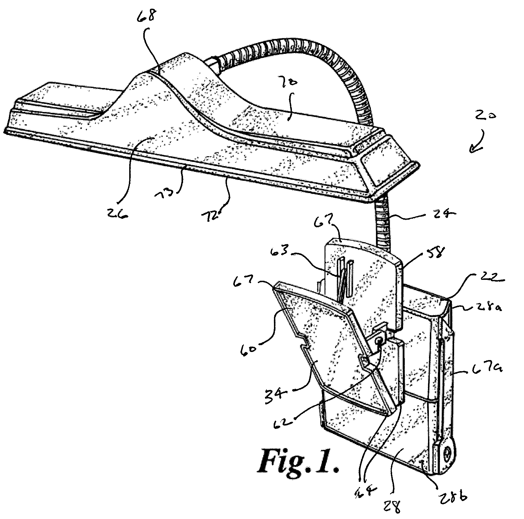
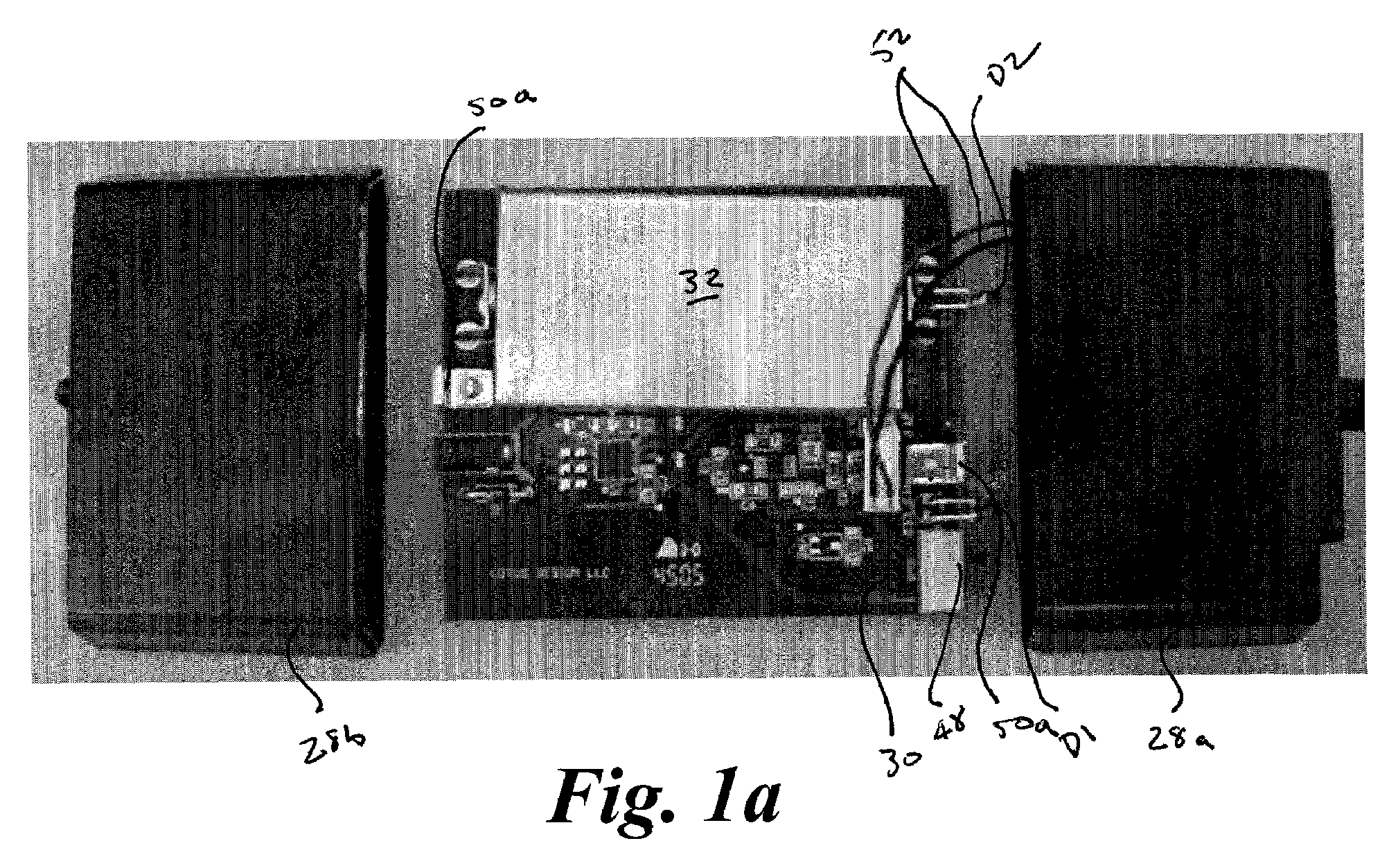
[0030]As depicted in FIGS. 1-10, an embodiment of the LED lamp 20 of the present invention generally includes power pack assembly 22, gooseneck 24, and shade assembly 26. Power pack assembly 22 generally includes housing 28, which may be formed in two halves 28a, 28b, and circuit board assembly 30, which may include battery 32, and attachment element 34. Housing 28 may be formed from lightweight polymer or other suitable material and is of sufficient size to house circuit board assembly 30 as well as other any electronics for lamp operation.

[0031]In an embodiment depicted schematically in FIG. 11, circuit board assembly 30 generally includes charging circuit 36 and regulator and light circuit 38. Charging circuit 36 functions to recharge rechargeable battery 32 from a power source, which may be a regulated DC adapter coupled with a 110V or 240V AC house system, connected through input jack 40. In an embodiment, charging circuit includes a Maxim / Dallas MAX1501ETE highly integrated, l...


PUM


Abstract

A battery powered LED lamp including an array of high-performance LEDs disposed in a lightweight directionally oriented shade. Converting electronics are provided which may include a step-down DC voltage switching regulator for converting a higher voltage of the battery power source to a lower voltage required to drive the LEDs at greater than 90% efficiency. The converting electronics may also include an LED current monitoring circuit for preventing thermal runaway of the LEDs and for reliably operating the LEDs near their maximum rating so to provide the maximum amount of brightness from the LED array and maximum battery life.

Description

RELATED APPLICATIONS[0001]This application claims the benefit of U.S. Provisional Patent Application No. 60 / 717,308, entitled BATTERY POWERED LED LAMP, filed Sep. 15, 2005, and hereby fully incorporated herein by reference.FIELD OF THE INVENTION[0002]The present invention relates to electronic lighting devices and more specifically to lighting devices using light emitting diodes (LEDs) as an illumination source.BACKGROUND OF THE INVENTION[0003]It is often desirable to use printed materials in low ambient light venues. For example, musicians sometimes need to read sheet music in performances at concerts, theatrical productions, clubs and other venues where house lighting may be low or non-existent. Further, it is sometimes desirable to read books and consult printed materials in locations where ambient lighting is insufficient for comfortable reading, as for example, at night in an automobile. Prior attempts at providing a lighting source for such venues have not been entirely succes...

Claims


Application Information

Patent Timeline
Patent Type & Authority Patents(United States)
IPC IPC(8): F21V21/14
CPCF21L4/04F21V21/088F21V21/0885F21V21/32
Inventor ANDERSON, GARYROTHMAN, RON
Owner ANDERSON GARY
Learn More