Imaging lens

a technology of imaging lens and pixel formation, applied in the field of imaging lens, can solve the problems of disadvantageous arrangement in view of small formation, and achieve the effects of reducing cost, high aberration function in correspondence, and high pixel formation

Active Publication Date: 2009-01-20
TIANJIN OFILM OPTO ELECTRONICS CO LTD
View PDF14 Cites 6 Cited by
  • Summary
  • Abstract
  • Description
  • Claims
  • Application Information

AI Technical Summary

Benefits of technology

[0006]An object of an illustrative, non-limiting embodiment of the present invention is to a small-sized and high function imaging lens sufficiently ensuring an interval of an inner portion for arranging a shutter mechanism while maintaining a high aberration function in correspondence with high pixel formation by using a lens material advantageous for a production performance and a reduction in cost.
[0008]The imaging lens can achieve small-sized formation by making shapes and refracting powers of the respective lenses with a constitution of a small number of 3 lenses as a total thereof. Further, by satisfying conditional equation (1), a power distribution of the first lens is optimized, which is advantageous for maintaining a high aberration function in correspondence with high pixel formation. Further, by satisfying conditional equation (2), the interval between the first lens and the second lens is widely ensured, which is advantageous for arranging a shutter mechanism. Further, by satisfying conditional equations (3) and (4), an increase in chromatic aberration is restrained while using a lens material advantageous for a production performance and a reduction in cost.
[0009]Further, the first lens may have a convex surface on the object side and at a vicinity of the optical axis thereof, and at least one of an object-side surface and an image-side surface of the first lens may be a diffracting surface. Thereby, higher function formation can be achieved. Particularly, even when constituted only by a material having a small difference between Abbe numbers of the respective lenses by satisfying conditional equation (4), chromatic aberration is excellently corrected.

Problems solved by technology

However, when a shutter mechanism is arranged before the first lens, the most object side, an arrangement becomes disadvantageous in view of small-sized formation.

Method used


Image

  • Imaging lens
  • Imaging lens
  • Imaging lens

Examples


Embodiment Construction

[0025]Although the invention will be described below with reference to the exemplary embodiments thereof, the following exemplary embodiments and modifications do not restrict the invention.

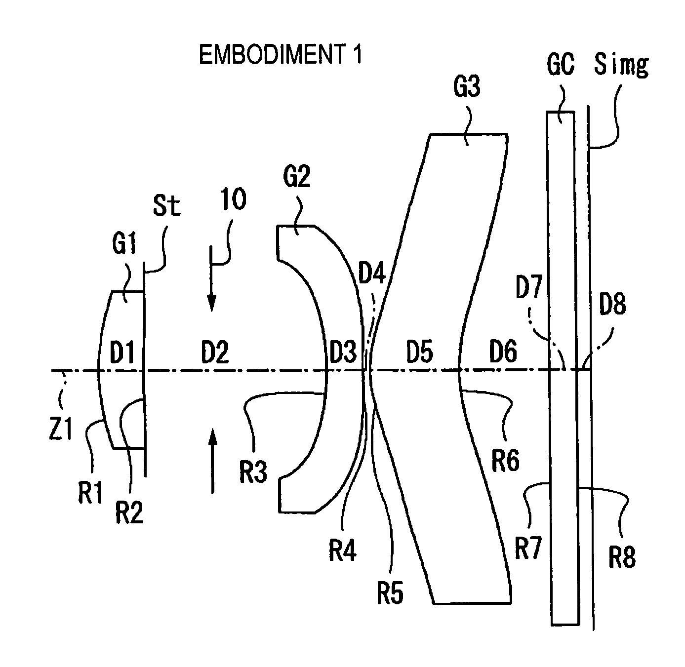
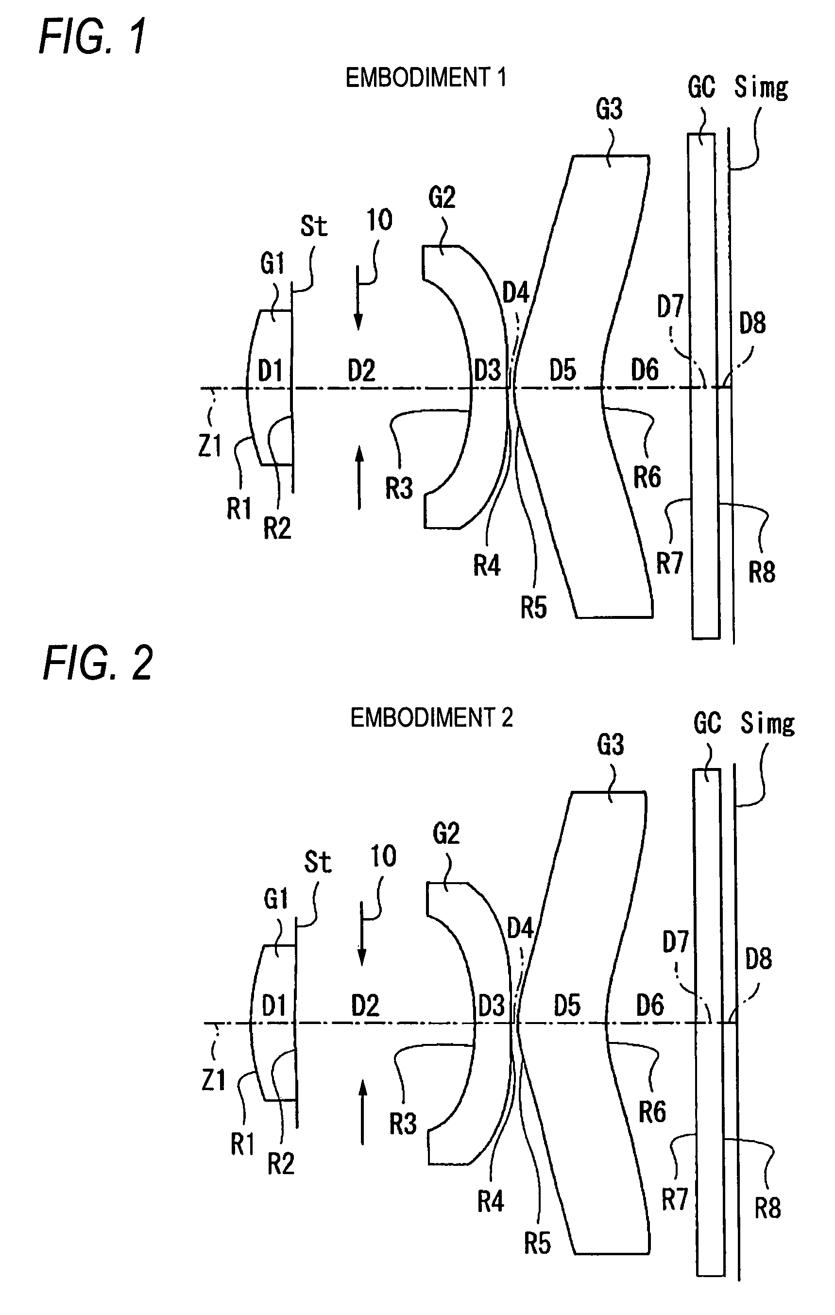
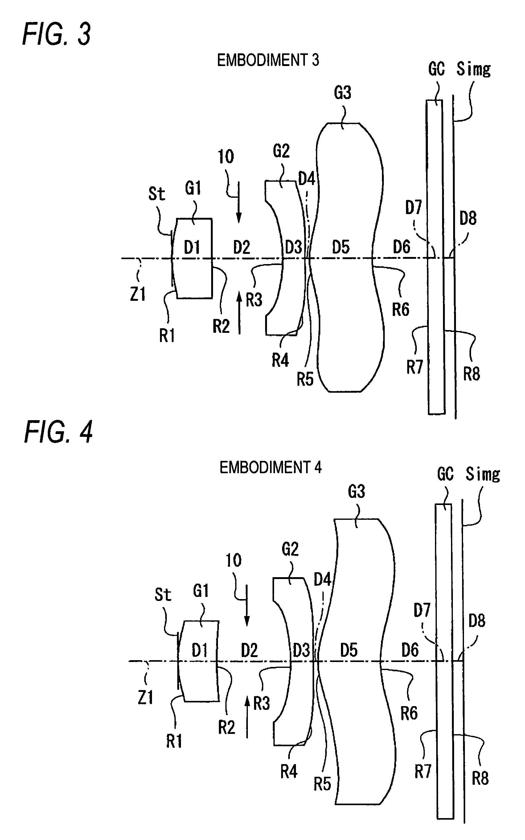
[0026]According to an image lens of the invention, materials of the respective lenses, shapes and refracting powers of the respective lenses, and arrangement of respective lenses are optimized by satisfying the conditional equations by the constitution having a small number of 3 lenses as a total thereof, and therefore, a small-sized high function lens system sufficiently ensuring an inner interval for arranging the shutter mechanism can be realized while maintaining the high aberration function in correspondence with the high pixel formation by using the lens material advantageous for the production performance and the reduction in cost. Further, particularly, when the first lens is provided with the diffracting surface, the chromatic aberration can excellently be corrected even when the respect...


PUM


Abstract

There is provided an imaging lens including a first lens having a positive refracting power, a second lens having a concave surface on an object side and having a negative refracting power, and a third lens having a positive refractive power and a meniscus shape having a convex surface on the object side and at a vicinity of an optical axis, in order from the object side. The imaging lens satisfies conditional equations below. f designates a focal length of the total system, f1 designates a focal length of the first lens, D2 designates an interval between the first lens and a second lens on an optical axis, ν123 designates an average of Abbe numbers of the first lens, the second lens and the third lens, and ν2 designates the Abbe number of the second lens.0.7<f1 / f<1.3  (1)0.25<D2 / f<0.50  (2)55<ν123  (3)|ν123−ν2|<5  (4)

Description

BACKGROUND OF THE INVENTION[0001]1. Field of the Invention[0002]The present invention relates to an imaging lens mounted to imaging apparatus using an imaging element of CCD (Charge Coupled Device), CMOS (Complementary Metal Oxide Semiconductor) or the like, for example, a digital still camera, a cellular phone with a camera, and an information portable terminal (PDA: Personal Digital Assistance) and the like.[0003]2. Description of Related Art[0004]According to an imaging element of CCD, CMOS or the like, in recent years, small-sized formation and high pixel formation have been considerably progressed. Therefore, also a main body of the imaging apparatus as well as a lens mounted thereto which are small-sized, having a high function are requested. In order to achieve small-sized formation, shortened formation of a total length and small diameter formation (small-sized formation in a diameter direction orthogonal to an optical axis) are needed. Further, generally, according to an im...

Claims


Application Information

Patent Timeline
Patent Type & Authority Patents(United States)
IPC IPC(8): G02B9/64G02B13/22
CPCG02B9/16G02B13/0035G02B13/18G02B9/14
Inventor SATO, KENICHITANIYAMA, MINORU
Owner TIANJIN OFILM OPTO ELECTRONICS CO LTD
Why Eureka
Try Eureka