Acoustic wave filter device

a filter device and wave technology, applied in piezoelectric/electrostrictive devices, piezoelectric/electrostrictive/magnetostrictive devices, electrical equipment, etc., can solve the problem of difficult to provide a pass band having a sufficient band width on the frequency side lower than the trap, and achieve the effect of sufficient band width and facilitate downsizing

Active Publication Date: 2009-01-20
MURATA MFG CO LTD
View PDF7 Cites 5 Cited by
  • Summary
  • Abstract
  • Description
  • Claims
  • Application Information

AI Technical Summary

Benefits of technology

[0010]To overcome the problems described above, preferred embodiments of the present invention provide an acoustic wave filter device which has a circuit configuration in which an acoustic wave resonator and an inductor facilitate downsizing, and which cannot only provide a trap providing a sufficient amount of attenuation, but also provide a pass band having a sufficient band width on the frequency side lower than the trap.

Problems solved by technology

However, the attenuation characteristic in a frequency band lower than the trap is flat, and thus, characteristics as a band-pass filter cannot be obtained on the lower frequency side.
However, with the trap filters disclosed in Japanese Unexamined Patent Application Publication No. 2004-129238 and in Japanese Unexamined Patent Application Publication No. 2003-332881, as described above, it is difficult to provide a pass band having a sufficient band width on the frequency side lower than the trap.

Method used


Image

  • Acoustic wave filter device
  • Acoustic wave filter device
  • Acoustic wave filter device

Examples


Embodiment Construction

[0039]The present invention will be described in detailed preferred embodiments of the present invention with reference to the drawings.

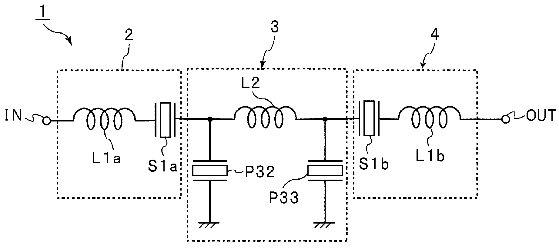
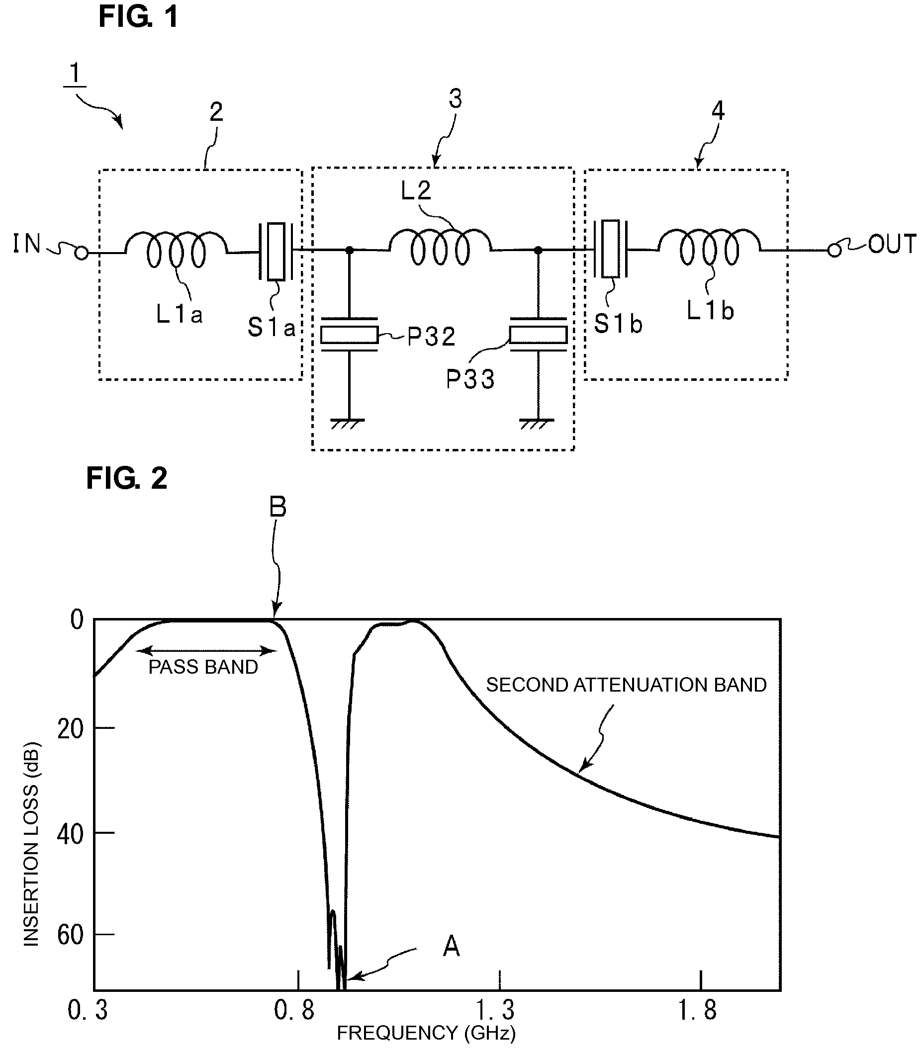
[0040]FIG. 1 is a circuit diagram of a surface acoustic wave filter device according to a preferred embodiment of the present invention. A surface acoustic wave filter device 1 of the present preferred embodiment is preferably used, for example, as a trap filter used in an RF stage of a mobile phone provided with a recording function for ground-wave digital television broadcasting. The surface acoustic wave filter device 1 preferably is configured to have a trap band around 880-915 MHz and a pass band including a frequency band around 470-750 MHz of ground-wave digital television DVB-H in a frequency range below about 800 MHz. The center frequency of the pass band is set as a first center frequency. The surface acoustic wave filter device 1 also has a second attenuation band on the frequency side higher than the first attenuation band set as the tra...


PUM


Abstract

In an acoustic wave filter device, a first filter circuit portion includes a first inductor provided in a series arm that couples an input terminal and an output terminal is serially connected to a first acoustic wave resonator, and a second filter circuit portion includes a second inductor provided in the series arm and second and third acoustic wave resonators and connected between one end and the other end of the second inductor and a ground potential. When the pass band center frequency is set as a first center frequency and the center frequency of a filter defined by the inductance of the first and second inductors and the capacitance of the first to third acoustic wave resonators is set as a second center frequency f2, f1 is less than f2.

Description

BACKGROUND OF THE INVENTION[0001]1. Field of the Invention[0002]The present invention relates to acoustic wave filter devices, such as surface acoustic wave filter devices and boundary acoustic wave filter devices. More specifically, the present invention relates to an acoustic wave filter device in which a plurality of inductors are connected between an input terminal and an output terminal and in which a plurality of resonators are connected between a series arm coupling the input terminal and output terminal and the ground potential.[0003]2. Description of the Related Art[0004]Conventionally, various surface acoustic wave filter devices are used as trap filters in RF stages of communication apparatuses, such as mobile phones. For example, Japanese Unexamined Patent Application Publication No. 2004-129238 discloses a trap filter including a plurality of inductances serially connected between an input terminal and an output terminal and parallel arm resonators each connected betwee...

Claims


Application Information

Patent Timeline
Patent Type & Authority Patents(United States)
IPC IPC(8): H03H9/00H03H9/54H01L41/08
CPCH03H7/01H03H9/6433H03H7/175
Inventor KURODA, KATSUHITO
Owner MURATA MFG CO LTD
Why Eureka
Try Eureka