Device for application of a line

Inactive Publication Date: 2009-01-20
LOREAL SA
View PDF15 Cites 14 Cited by
  • Summary
  • Abstract
  • Description
  • Claims
  • Application Information

AI Technical Summary

Benefits of technology

[0009]There is a need to provide a packaging and applicator device of simple design enabling convenient and repeatable application of a fluid product directly in the form of a line. To this end, a preferred embodiment of the invention includes an applicator, preferably flexible and of elongated shape extending between two points, these two points being preferably located at the end of two arms mounted on a handle of the device. The device can also include a reservoir of product capable of recharging the applicator, for example between two uses. Preferably, the flexibility of the arms combined with pliability of the applicator enables the product to be applied in a convenient manner while needing to grasp the handle with only one hand.
[0010]Furthermore, the makeup actions associated with a device according to a preferred embodiment of the invention can confer greater visibility, in that the handle can be held and oriented parallel to an axis on which the applicator is brought into proximity with the area to be coated.
[0011]Preferably, the user applies a first end of the applicator, located in proximity to a point of attachment of this applicator to one end of the arm, onto the skin at a desired starting point for the line. The applicator is then brought down so as to progressively apply the line onto the skin. In the case where the surface to be coated is curved, the applicator can be flexible. Furthermore, the length of the applicator can be adapted by making it elastically deformable. The user thus applies a line between the two ends of the arms, or a portion of the line only, onto the skin. The flexibility of the arms also confers a degree of softness to the application, the pressure exerted on the surface to be coated being thereby diminished.
[0014]In another embodiment, the packaging includes a reservoir containing the product and capable of charging the applicator. The grasping element incorporates a connection to the reservoir in a position preventing the applicator from being charged when the latter is applied against the application surface.
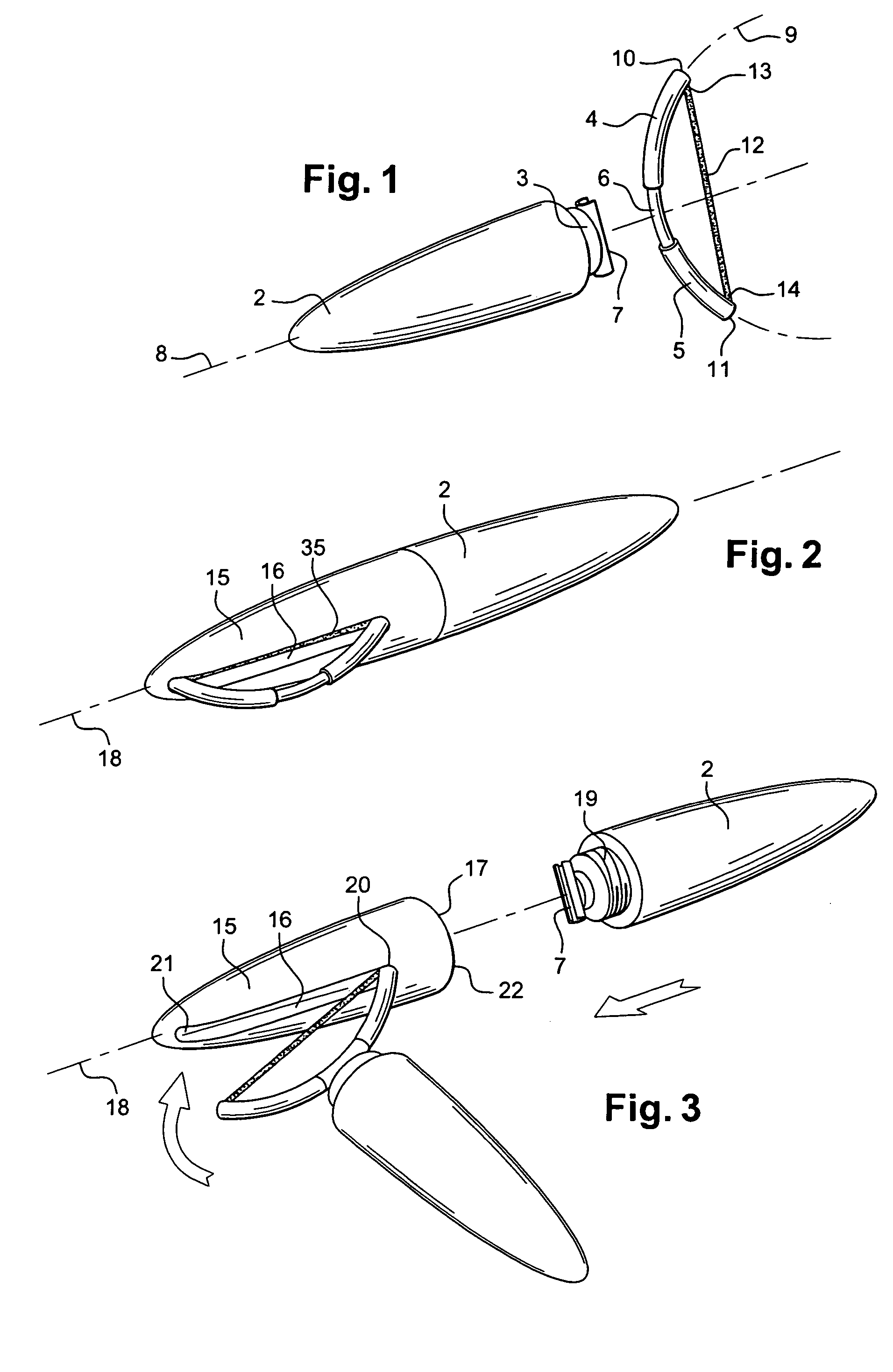
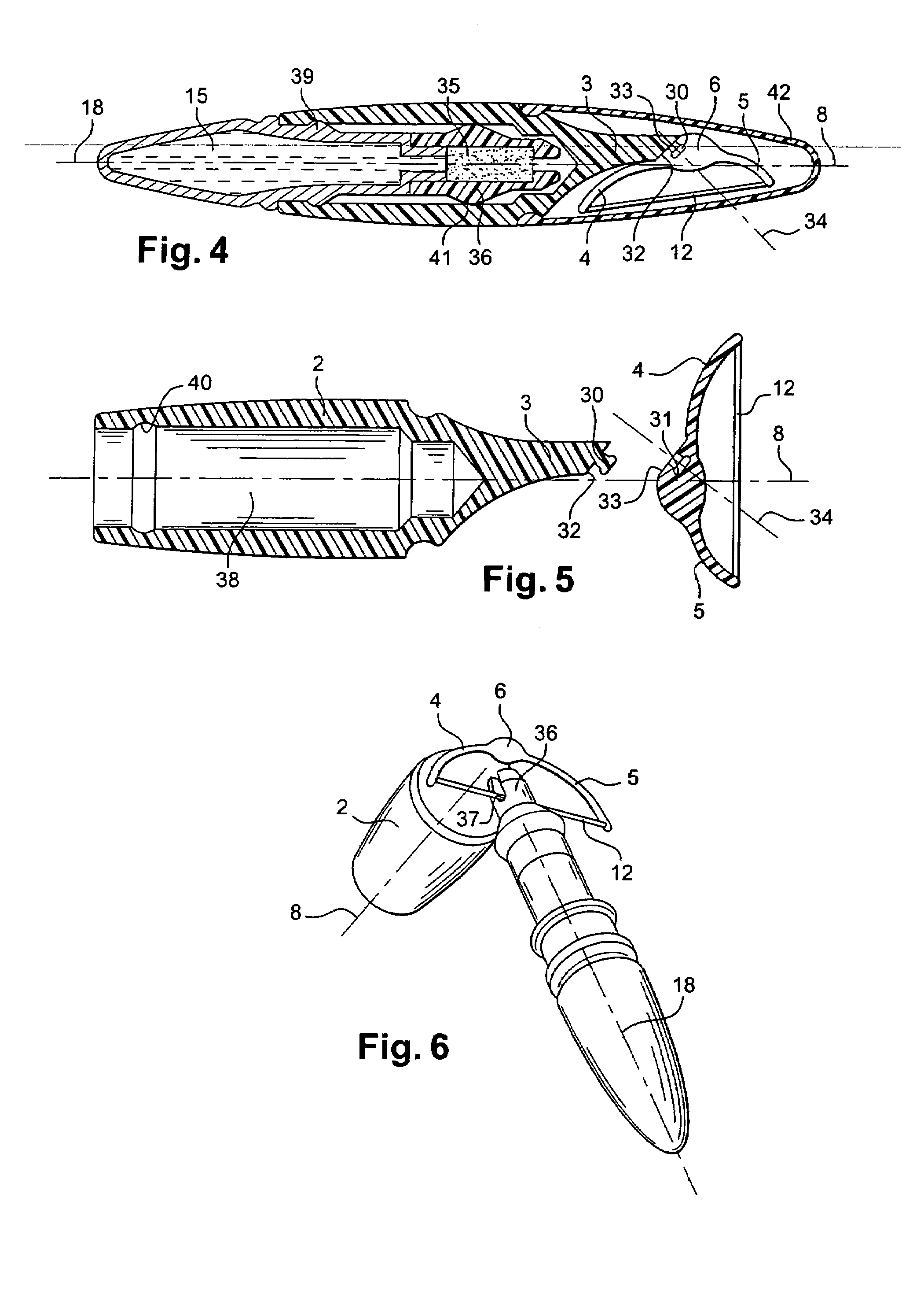
[0027]In an advantageous embodiment of the invention, the two arms can be mounted integrally and rotatably on the grasping element about a fixed axis of rotation. The axis of rotation can form a non-zero angle, for example, in the order of 45°, with a principal lengthwise axis of the grasping element. The axis of rotation and the principal lengthwise axis can be secant or non-secant at the level of a junction between the two arms and the grasping element. In this variant, by rotating the two arms relative to the grasping element, the user can modify the angle formed between the principal lengthwise axis and a plane passing through the two arms.
[0032]For example, at least one projection can be made on at least one of the surfaces at the grasping element and the two arms to enable a user to more readily immobilize the grasping element in a predefined angular position relative to the two arms.

Problems solved by technology

This make-up operation can be difficult to perform without mistakes.
The line obtained often includes unwanted deviations.
The eye makeup procedure taught by this document is not adaptable.
Given that the applicator is preformed to match the external outline of an average eyelid, it is not suitable for all users.
This type of applicator poses a drawback in that it obliges the user to contract her hands and to hold this contracted position during application of the false lashes.
Moreover, in cases where the applicator is held in a convex shape, the false eyelash is then more difficult to detach from its adhesive carrier.

Method used


Image

  • Device for application of a line
  • Device for application of a line
  • Device for application of a line

Examples


Embodiment Construction

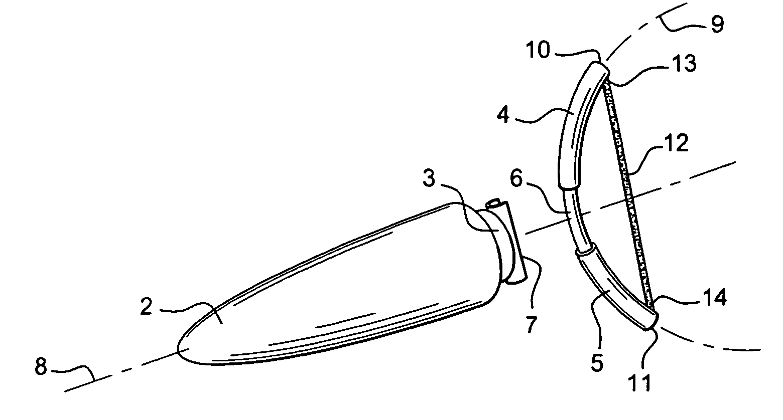
[0048]FIG. 1 shows an applicator device 1 according to a preferred embodiment of the invention. The device 1 includes a grasping element 2, also termed the handle 2 in the following description, at one end 3 of which are disposed two arms, preferably flexible, respectively 4 and 5. The arms 4 and 5 are assembled one to the other in proximity to a grasping zone 6 connected to the end 3 of the handle 2. The grasping element 2 has a principal lengthwise axis 8. The arms 4 and 5 carry an applicator 12.

[0049]In the variant shown in FIG. 1, the handle 2 is detachable from the arms 4 and 5. The handle 2 includes a retention mechanism 7 at its end 3 designed to cooperate with the grasping zone 6. Preferably, this retention mechanism 7 is resilient so as to be attachable and / or detachable from arms 4 and 5 in a reversible manner. In a reciprocal manner, the end 3 can include an engagement mechanism with a retention mechanism presented by the zone 6. For example, the end 3 defined on the gras...


PUM


Abstract

An applicator device includes a grasping element, two arms mounted on the grasping element and an applicator between the two arms. The applicator can apply a product in the form of a line onto a surface. The device can additionally include a reservoir containing the product such that the grasping element incorporates a mechanism to hold the reservoir in a position preventing the applicator from being charged when the latter is applied against the application surface.

Description

CROSS REFERENCE TO RELATED APPLICATIONS[0001]This document claims priority to French Application Number 03 04572, filed Apr. 11, 2003 and U.S. Provisional Application Ser. No. 60 / 470,505, filed May 15, 2003, the entire contents of which are hereby incorporated by reference.BACKGROUND OF THE INVENTION[0002]1. Field of the Invention[0003]The present invention relates to devices for the application of a line, for example for applying a line onto a surface using a cosmetic product. The invention can be used in the field of cosmetic applicators such as liners, also termed “eyeliners,” used to make a continuous or discontinuous line on the edge of the eyelid. The line applied can emphasize the outline of the eyes, and modify the eyeline and the apparent size of the eyes.[0004]2. Discussion of Background[0005]In known “eyeliners,” the applicator, in the form of a point, is mounted at the end of a rod fixed in a cap. This cap is designed to be fitted on a reservoir holding product in a mann...

Claims


Application Information

Patent Timeline
IPC IPC(8): A46B11/00A45D40/26
CPCA45D40/26A45D2200/1072
Inventor RAMET, MARC
Owner LOREAL SA
Why Eureka
Try Eureka