Vehicle equipped with lift device and lift device

a technology of lifting device and lift device, which is applied in the field of lift device, can solve the problems of not being able to quickly unload, and being dangerous, and achieve the effect of safe raising and lowering objects

Inactive Publication Date: 2009-01-13
SATO KOGYOSYO
View PDF13 Cites 3 Cited by
  • Summary
  • Abstract
  • Description
  • Claims
  • Application Information

AI Technical Summary

Benefits of technology

[0030]By virtue of the lift device according to the present invention, it is possible to suitably lower an object, which is supported by the support link that connects the pair of slide arm members, from a high surface to a predetermined position, by swinging the first telescoping arm and the second telescoping arm between a standby position within the area of a high surface, such as the top of a vehicle, and a deployed position outside the area of the high surface by the swinging movement of the drive boom, so as to be vertically inverted while being maintained parallel to each other, and in the deployed position, the slide arm members of the first telescoping arm and the second telescoping arm being acted upon by gravity so as to extend in a downward movement from the base arm members, so as to reduce the radius of swing of the drive boom and the follow boom.
[0031]In addition, at least one of the first telescoping arm or the second telescoping arm is provided with a slowing fluid-pressure cylinder for moderating the telescoping speed of the arms, whereby it is possible to safely raise and lower objects without the objects descending rapidly.
[0032]Moreover, the fluid-pressure cylinder is a double acting cylinder wherein a flow regulating valve is provided in a conduit line that connects ports at the head and the bottom, allowing the telescoping speed of the fluid-pressure cylinder to be controlled without complex circuits.

Problems solved by technology

However, each time that objects are loaded onto or taken down from these high surfaces, it is necessary to go up to this high surface and pass the objects up and down, which is bothersome and may be dangerous.
In particular, when rescue ladders and boats are loaded on the top of a vehicle body, there is a problem in that they cannot be quickly unloaded, even if there is urgent need for their use.
Furthermore, crane systems are capable only of reducing human labor, and cannot be expected to greatly reduce the time required for loading and unloading; nor are these systems suitable for firefighting and the like, where speed is vital.
This presents a problem in that the swing radius of the swing arm increases so that, when working in an enclosed space having a low ceiling or beneath overhead wires, the swing arm or the top of the carrier may collide with obstacles such as ceilings or overhead wires when the swing arm is swung.
But, the center of swing of the swing arm is on the top of the vehicle, and the swing arm only swings up and down on the top of the vehicle, so that even if the length of the swing arm is increased, if the carrier is short, it is not possible for that carrier to hold long objects.
Further, if the vehicle is high, with respect to the length of the carrier, it is not possible to lower the carrier to a position at which objects can be removed.

Method used


Image

  • Vehicle equipped with lift device and lift device
  • Vehicle equipped with lift device and lift device
  • Vehicle equipped with lift device and lift device

Examples


Embodiment Construction

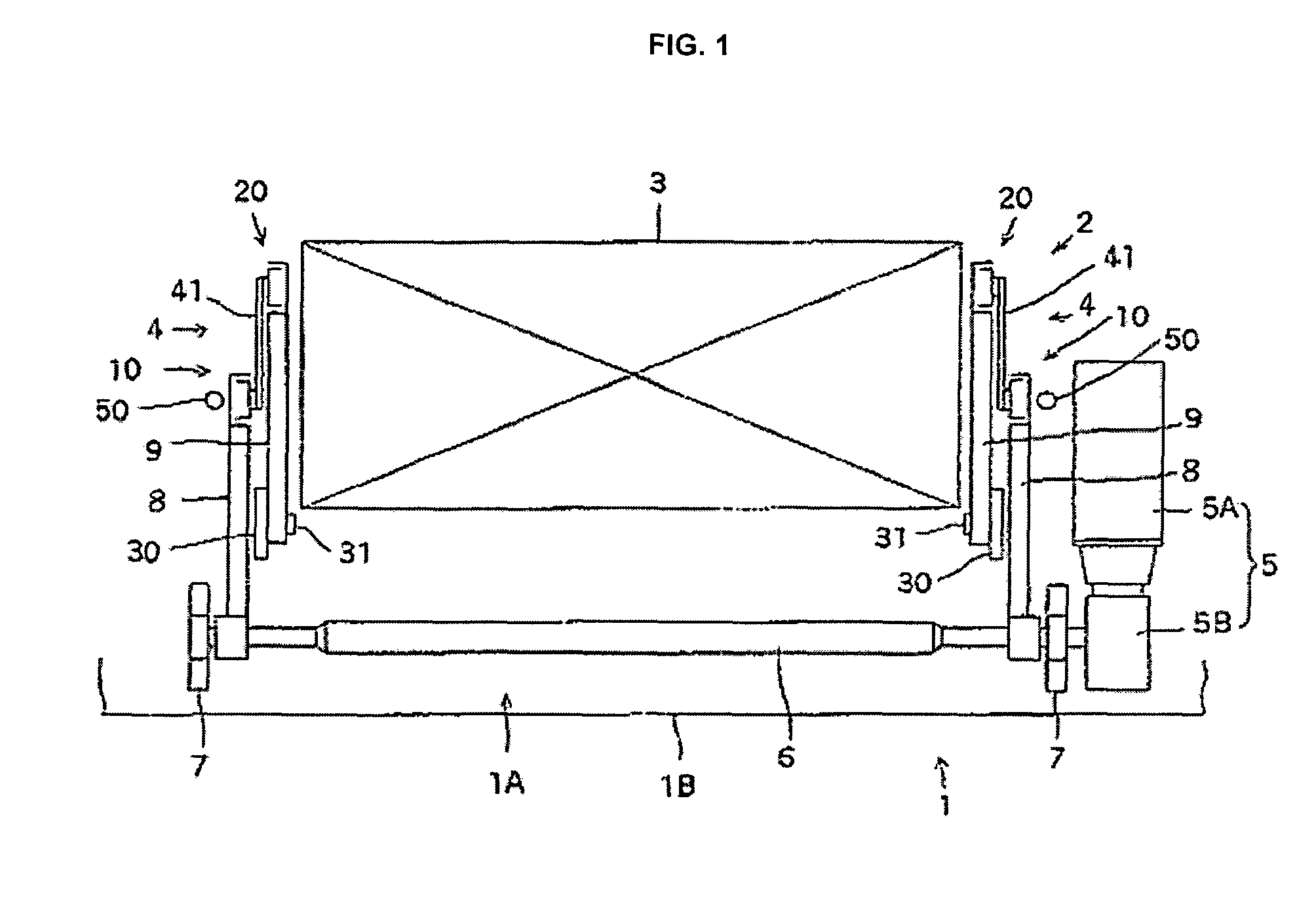
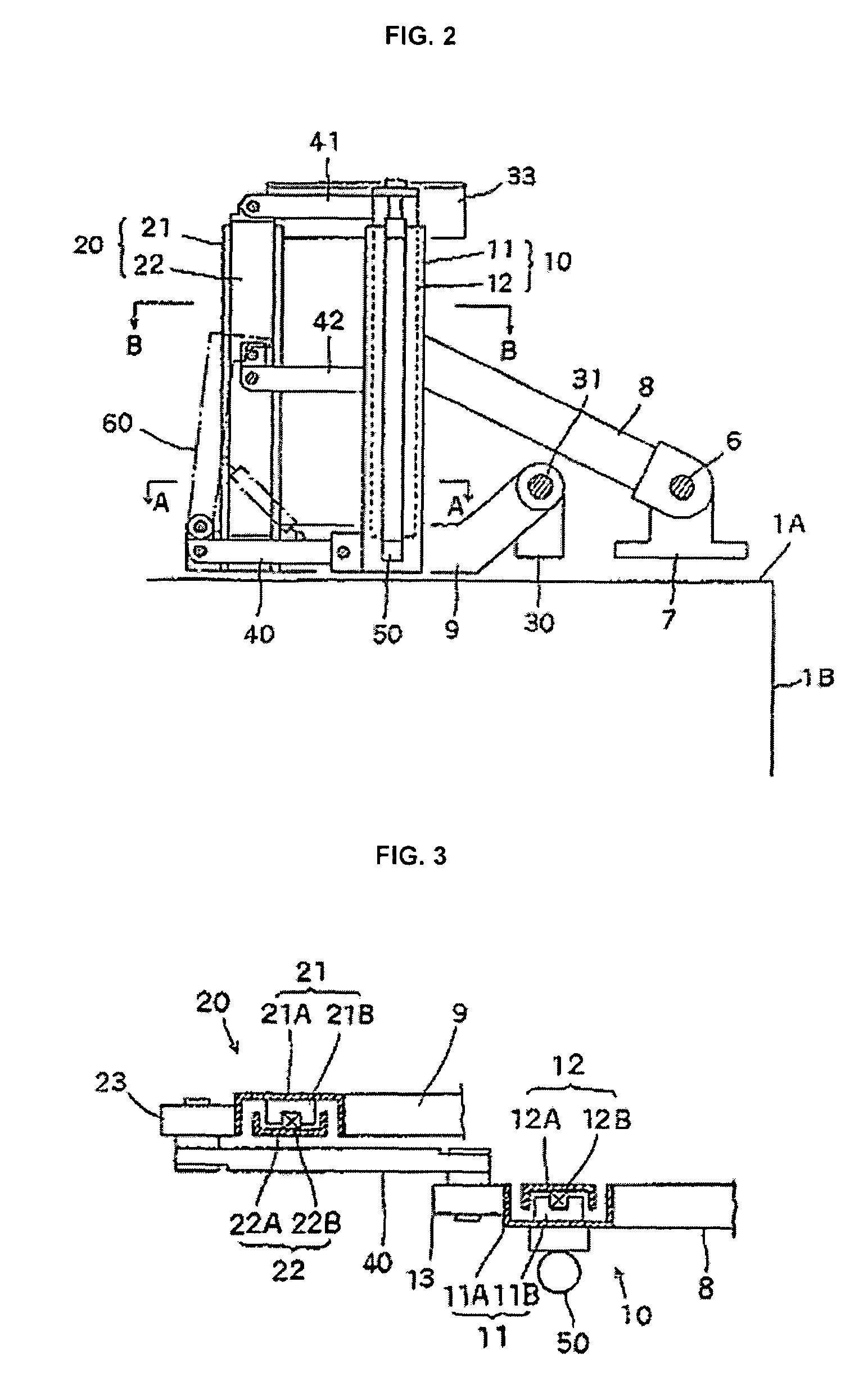
[0046]Hereinafter, the present invention will be described in further detail with reference to the drawings. FIG. 1 is a partial plane view illustrating a vehicle (and particularly a firefighting vehicle) provided with a lift device according to the present invention. In FIG. 1, reference numeral 1 indicates a box shaped vehicle, equipped with a lift device 2 on the top 1A thereof, for loading and unloading objects from one of the lateral faces 1B of the vehicle.

[0047]The lift device 2 comprises a pair of front and back link units 4, 4, which are disposed parallel to each other with a predetermined space therebetween, on either side of a carrying frame 3, in the front-back direction, on the top 1A of the vehicle, which is the high surface, and a single drive source 5 for driving these link units 4, 4. The drive source 5 comprises a reversible drive motor 5A, which is disposed adjacent to one of the link units 4, and a reducer 5B for increasing the rotational torque thereof. Note tha...


PUM


Abstract

A vehicle equipped with a lift device, capable of suitably lowering objects that have been placed in a high place to a position at which they can be reached by people, is provided. A link unit is provided on the top of the vehicle. The link unit is comprised of telescoping arms, which are parallel to each other. The link unit is comprised of base arm members, slide arm members, a base link which connects the base arm members, and support links, which are parallel to the base links and which connect the slide arm members. Further, the link unit is comprised of a drive boom, which is swung up and down on the top of the vehicle around a drive shaft, and a follow boom, which is swung, in the same direction as the drive boom, around a support shaft that is parallel to the drive shaft. One base arm member is attached to the leading end of the drive boom, and another base arm member is attached to the leading end of the follow boom.

Description

FIELD OF THE INVENTION[0001]The present invention relates to a lift device that can quickly and easily raise and lower an object that is disposed on a high surface. More specifically, it relates to a lift device and to a vehicle equipped with a lift device that is optimal for use in loading and unloading large loads onto the tops of vehicles.BACKGROUND OF THE INVENTION[0002]High surfaces, which represent dead space, are commonly advantageously used for storage of objects of various different types. For example, rescue ladders and folding boats are often loaded on the top of firefighting vehicles and used to rescue people.[0003]However, each time that objects are loaded onto or taken down from these high surfaces, it is necessary to go up to this high surface and pass the objects up and down, which is bothersome and may be dangerous.[0004]In particular, when rescue ladders and boats are loaded on the top of a vehicle body, there is a problem in that they cannot be quickly unloaded, e...

Claims


Application Information

Patent Timeline
Patent Type & Authority Patents(United States)
IPC IPC(8): B62D43/00
CPCB60P3/1016Y10S414/13
Inventor ITO, HIDEAKI
Owner SATO KOGYOSYO
Why Eureka
Try Eureka