
Foil slot impingement cooler with effective light-trap cavities

a cooler and air slot technology, applied in indirect heat exchangers, semiconductor/solid-state device details, lighting and heating apparatus, etc., can solve the problems of insufficient heat removal speed for high-power devices that produce very large heat fluxes, warp and possibly fail of solid-state devices, etc., to avoid large transverse temperature gradients, reduce heat loss, and reduce heat loss

Active Publication Date: 2009-01-06
RAYTHEON CO
View PDF19 Cites 18 Cited by
  • Summary
  • Abstract
  • Description
  • Claims
  • Application Information

AI Technical Summary

Benefits of technology

[0013]The slot impingement cooler directs a large flow of coolant against the cooled surface to remove a large amount of heat. It achieves a uniform impingement cooling over the cooled surface, avoiding large transverse temperature gradients. Both sensible heat and radiative heat are removed by the present approach. The slot impingement cooler may be readily scaled in size by adding more foil sets and / or making each foil set longer. The slot impingement cooler is also readily manufactured in quantity by foil etching of the individual foils, stacking the etched foils, and cutting the stacks.

Problems solved by technology

Additionally, the large amount of locally produced heat creates internal strains that cause the solid-state device to warp and possibly fail, if the heat is not removed.
The heat may also cause damage to adjacent devices.
While such confined-flow heat exchangers are operable, experience has shown that they cannot remove heat sufficiently rapidly for high-power devices that produce very large heat fluxes.
The result is that the ability to remove large amounts of heat is limited, unless the flow rate of coolant is so high as to be impractical for many situations.
Additionally, there are periodic temperature gradients across the surface being cooled, resulting in undesirable transverse thermal strains in the solid-state device.

Method used


Image

  • Foil slot impingement cooler with effective light-trap cavities
  • Foil slot impingement cooler with effective light-trap cavities
  • Foil slot impingement cooler with effective light-trap cavities

Examples


Embodiment Construction

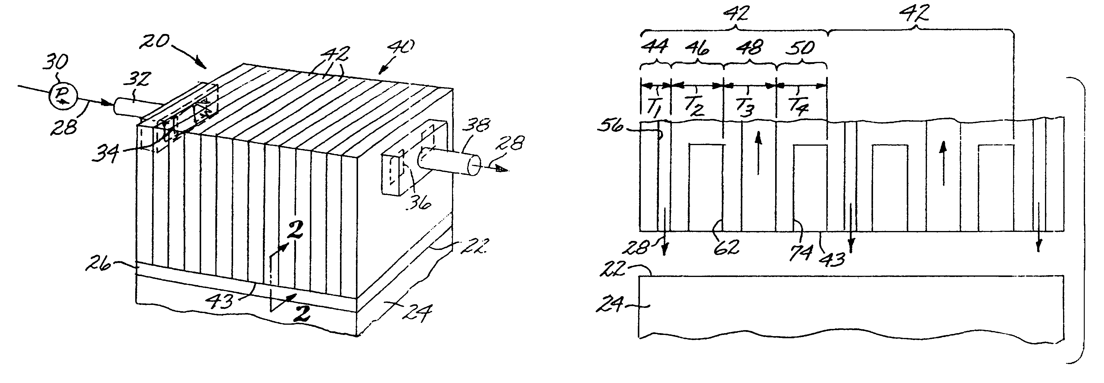
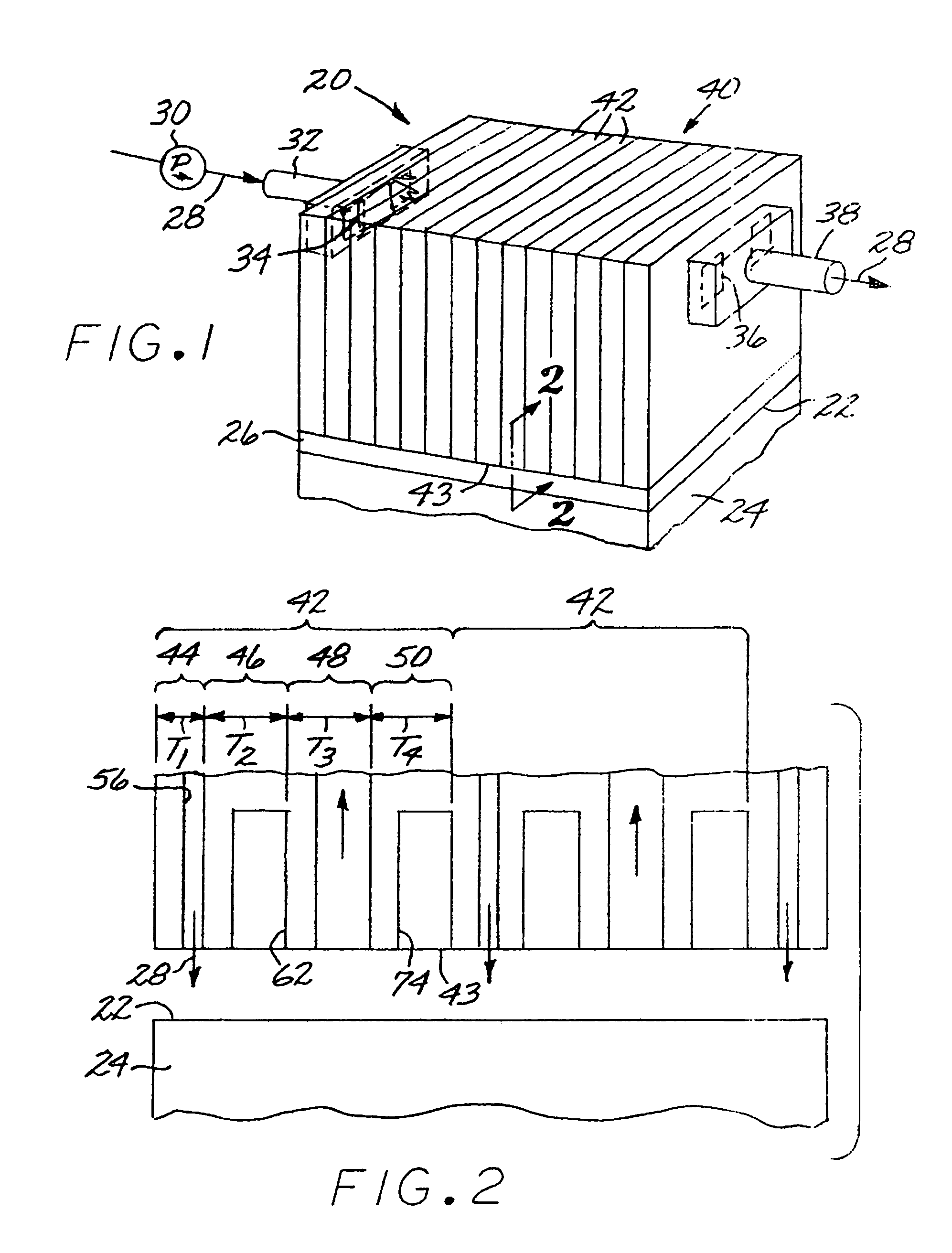
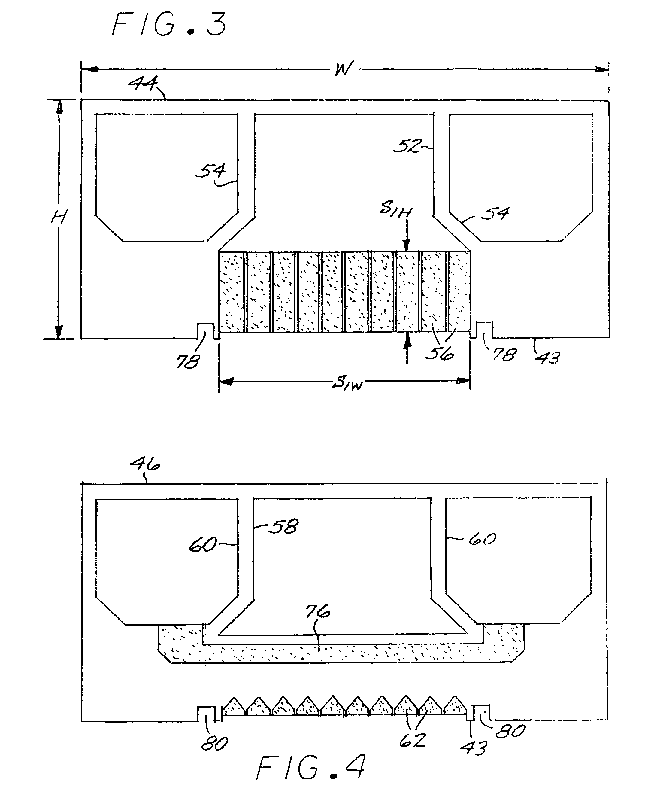
[0019]FIG. 1 depicts a slot impingement cooler 20 cooling a cooled surface 22 of a cooled article 24. The slot impingement cooler 20 is sealed to the cooled surface 22 by a seal ring 26 extending around the periphery of the slot impingement cooler 20. A flow of a coolant 28 pressurized by a pump 30 is supplied to the slot impingement cooler 20 by a supply line 32 feeding a supply manifold 34 within the slot impingement cooler 20. After cooling the cooled surface 22, the coolant 28 is removed through a return manifold 36 of the slot impingement cooler 20 that drains to a return line 38. The coolant 28 may be a liquid or a gas, and the cooling process may be single phase or dual-phase. The preferred coolant 28 is liquid water that remains in liquid form as it passes through the slot impingement cooler 20.

[0020]The slot impingement cooler 20 is formed of a foil set 40 that comprises at least one, and typically a plurality of, sets 42 of foils. The individual foils are thin sheets, pref...


PUM


Abstract

A slot impingement cooler is formed of a plurality of sets of foils in a stacked and registered array. In each set of foils, a first foil has supply slots that direct a flow of coolant, a second foil has a plurality of effective light-trap cavities, a third foil has return slots that return the flow of coolant, and an optional fourth foil has a plurality of effective light-trap cavities. The foils have registered supply manifold openings and registered return manifold openings therethrough.

Description

[0001]This invention relates to an impingement cooler and more particularly, to a slot-jet impingement cooler having a foil construction and which includes effective light traps to trap, absorb, and dissipate light energy.BACKGROUND OF THE INVENTION[0002]Some solid-state devices produce a large waste-heat output in a small area during operation. The heat may be produced in two forms, sensible heat and light-energy heat. The heat must be removed rapidly when the solid-state device is in operation so that its maximum operating temperature is not exceeded. Additionally, the large amount of locally produced heat creates internal strains that cause the solid-state device to warp and possibly fail, if the heat is not removed. The heat may also cause damage to adjacent devices. An example of a solid-state device having these concerns is a solid-state laser whose laser amplifier chain laser gain media consists of a number of rectangular amplifier slabs that produce heat energy at their surf...

Claims


Application Information

Patent Timeline
Patent Type & Authority Patents(United States)
IPC IPC(8): F28D21/00H01S3/04
CPCH01L23/4735H01S3/0407H01S3/042H01L2924/0002Y10S165/908Y10S165/904H01L2924/00
Inventor JOHNSON, SCOTT T.SCHROEDER, JOHN H.FILGAS, DAVID
Owner RAYTHEON CO
Learn More