Method and apparatus for gas management in hot blow-forming dies

a technology of gas management and hot blowing, applied in the field of articles, can solve the problems of affecting the production efficiency of components made from this material, affecting the production efficiency of components, and affecting the quality of components produced by superplastic forming processes, so as to improve the control of wrinkles, prevent the wrinkling of finished parts, and reduce tolerances

Active Publication Date: 2009-01-06
FORD GLOBAL TECH LLC +1
View PDF12 Cites 2 Cited by
  • Summary
  • Abstract
  • Description
  • Claims
  • Application Information

AI Technical Summary

Benefits of technology

[0014]An aspect of the present invention is to prevent the wrinkling of the finished part. This is achieved in part by providing a punch having side walls which are large relative to the inner forming surface of the upper die and the restraining walls of the blankholder. Using this configuration the gaps between the side walls of the punch and the inner forming surface of the upper die are reduced thus achieving a pre-form having edges that are more sharply defined than known in prior approaches to superplastic forming. Furthermore, the gap between the punch and the metal restrained in the blankholder is essentially removed, thus allowing better control of wrinkles. An additional aspect of having reduced tolerances between the walls of the punch and the inner forming surface of the upper die is that the pre-form (and hence the finished part) displays fewer wrinkles than those produced according to known technologies.

Problems solved by technology

However, the expanded application of components made from this material is being hampered because of its limited temperature formability.
Superplastic forming can result in very deep components which would rupture during the formation process by using conventional methods.
As a result, the components produced by superplastic forming processes can embody relatively complex and highly integrated configurations.
Furthermore, the low forces needed to form the material at these elevated temperatures allows for the use of cast iron dies instead of the harder to work and more expensive tool steel.
While superplastic forming may be a viable manufacturing option for some parts, there are limitations in the economic feasibility of this technique.
This results in a relatively slow cycle time which often leaves superplastic forming as a cost-prohibitive option for parts having volumes greater than 1000 parts per year.
Another problem related to SPF stems from the inability to draw material into the die cavity.
Although the superplastic material utilized in SPF can undergo substantial deformation, its formability is limited to the amount of material in the die.
This may result in tears or inconsistent wall thickness in the part being formed.
While the method of this patent teaches pre-forming the material before the gas is injected, the method does not restrain the material entering the die during the pre-forming step.
Wrinkling of the material during pre-forming will result in either the inability to complete the part during subsequent gas pressure forming or, at best, a low quality finished part.

Method used


Image

  • Method and apparatus for gas management in hot blow-forming dies
  • Method and apparatus for gas management in hot blow-forming dies
  • Method and apparatus for gas management in hot blow-forming dies

Examples


Embodiment Construction

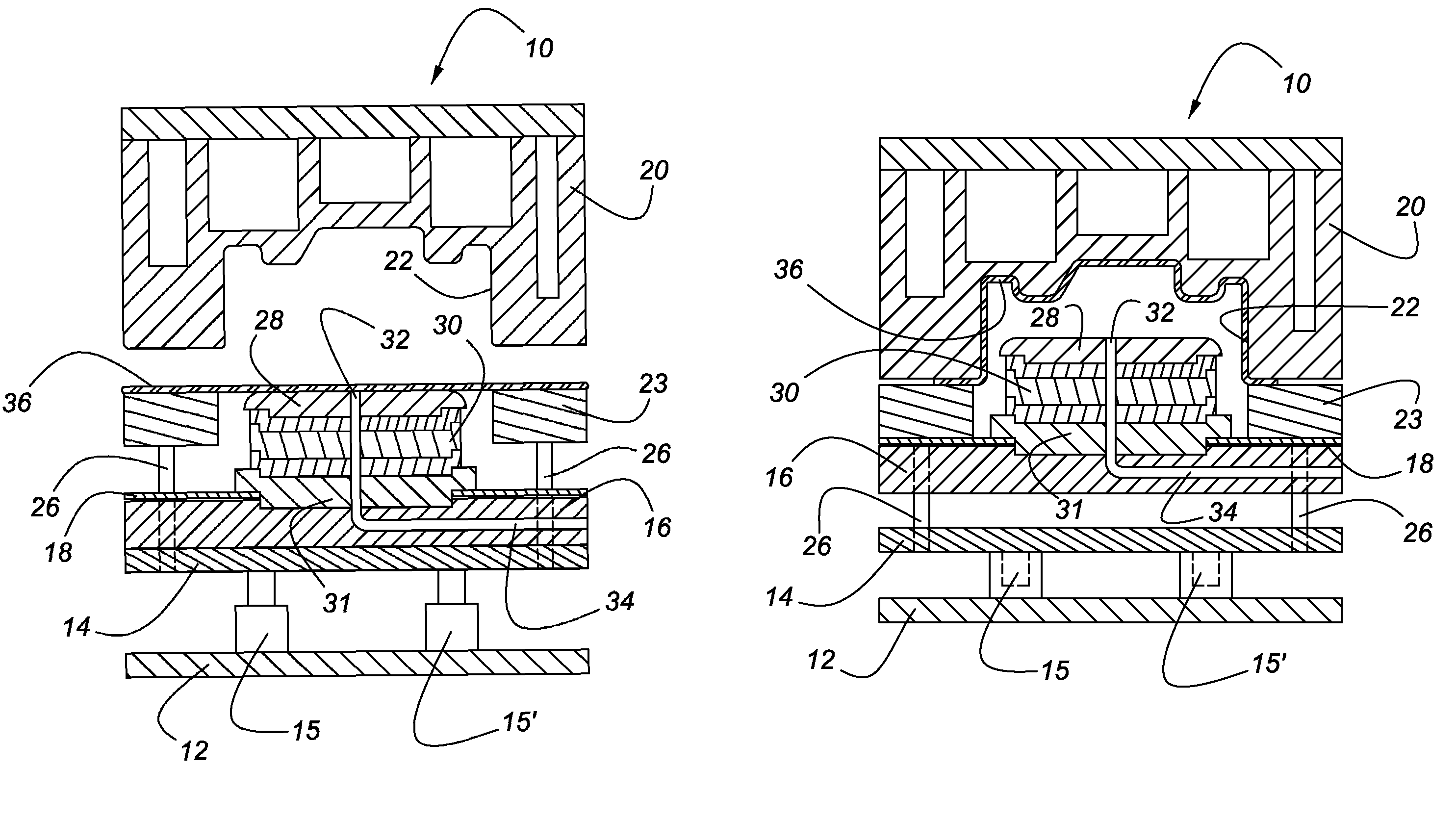
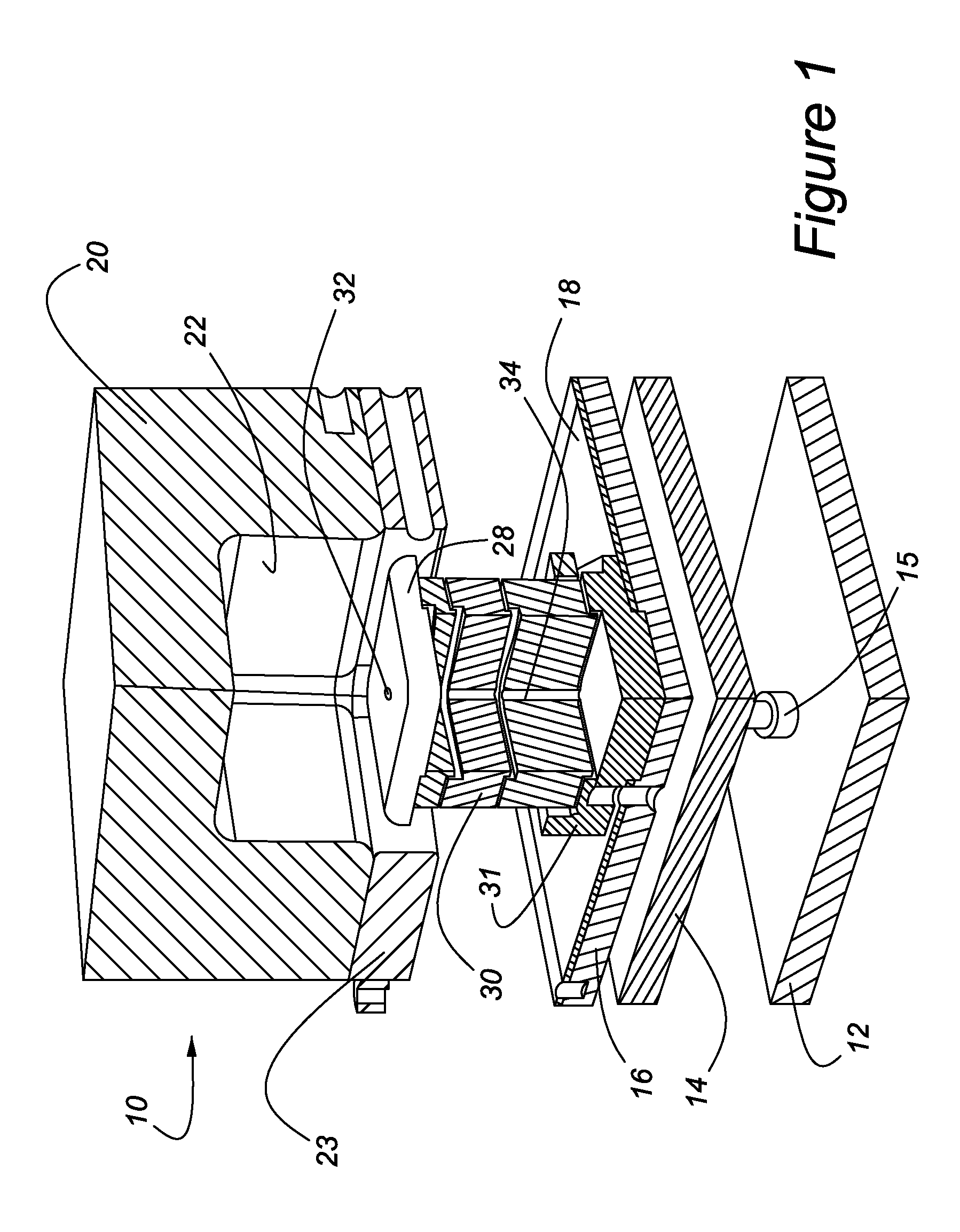
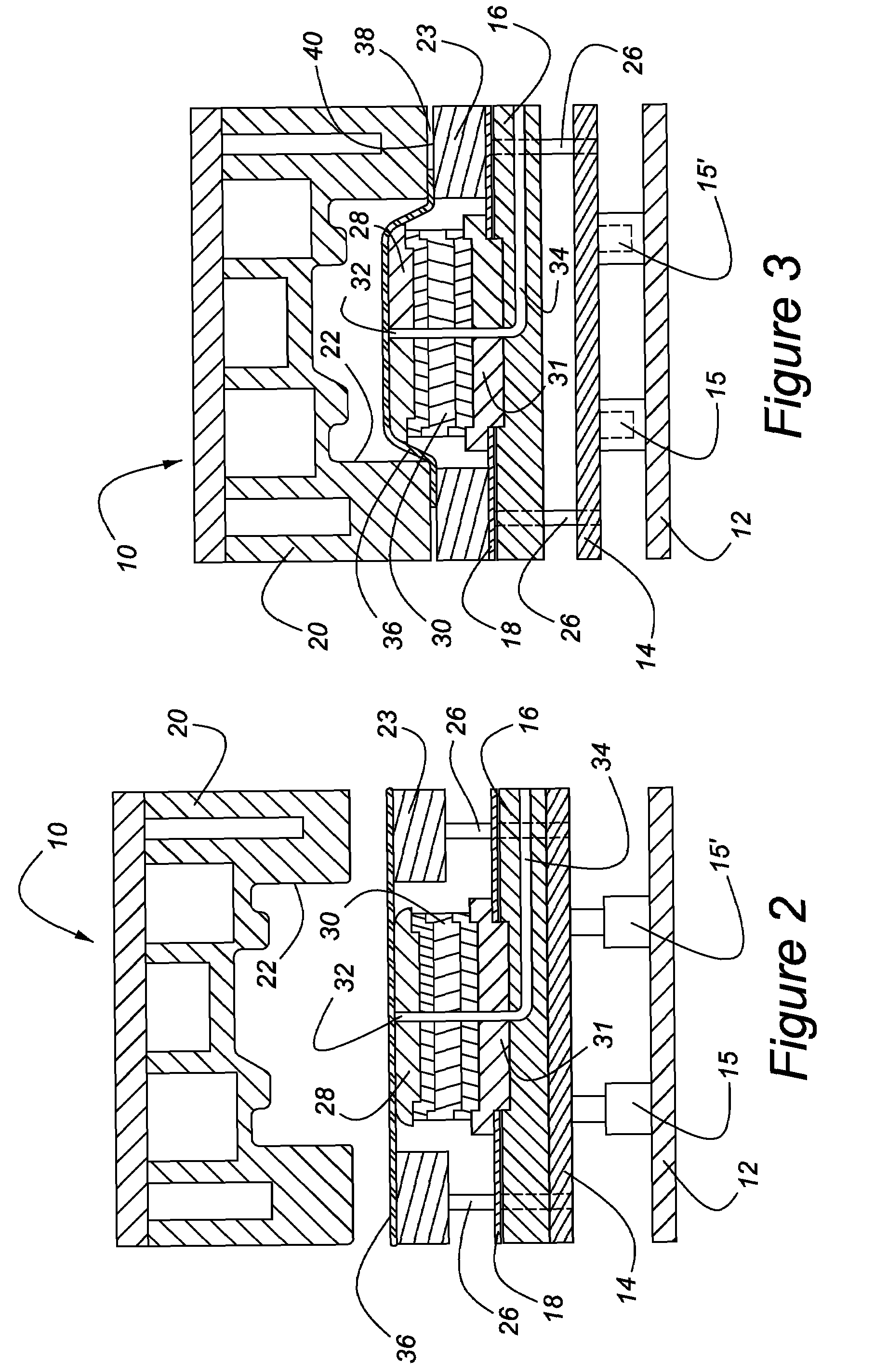
[0022]In the following figures, the same reference numerals will be used to refer to the same components. In the following description, various operating parameters and components are described for one constructed embodiment. These specific parameters and components are included as examples and are not meant to be limiting.

[0023]With reference to FIGS. 1, a quarter section view of a double-action mechanical pre-forming die apparatus for superplastic forming of a sheet of highly ductile material in accordance with the present invention, generally illustrated as 10, is shown. The superplastic forming apparatus 10 includes a press base 12 which is fixedly mounted on a surface such as a floor (not shown). Spaced apart from the press base 12 is a movable cushion plate 14. Referring to FIGS. 1 through 4, the cushion plate 14 is movably supported by the press base 12 by one or more cylinders 15 and 15′. Two cylinders are shown, but it is understood that more cylinders can be used, dependin...


PUM

PropertyMeasurementUnit
temperatureaaaaaaaaaa

Abstract

A method and apparatus for forming a sheet of ductile material by superplastic forming is disclosed. The method is directed to first creating a pre-form by mechanical forming in which the pre-form is created with a die and punch. Thereafter the pre-form is subjected to gas pressure in a forming cavity to complete formation of the part. A metallic gasket is provided to ensure that no pressurized gas escapes from the forming cavity.

Description

TECHNICAL FIELD[0001]The present invention relates generally to the production of articles using superplastic forming. More particularly, the present invention relates to a method and apparatus utilizing a first step in which a pre-form is created with a die and punch and a second step in which the pre-form is subjected to gas pressure in a forming cavity to complete formation of the part. A metallic gasket is provided to ensure that no pressurized gas escapes from the forming cavity.BACKGROUND OF THE INVENTION[0002]The use of aluminum components in motor vehicles continues to expand due to the relatively good strength-to-weight ratio of this material. However, the expanded application of components made from this material is being hampered because of its limited temperature formability. One increasingly popular method of producing components from aluminum is superplastic forming in which certain materials, including particularly aluminum, are heated (under controlled temperature) a...

Claims


Application Information

Patent Timeline
Patent Type & Authority Patents(United States)
IPC IPC(8): B21D26/02
CPCB21D22/205Y10T29/49805B21D22/208B21D22/22B21D26/021B21D26/055
Inventor LUCKEY, JR., GEORGELUO, YINGBINGFRIEDMAN, PETER
Owner FORD GLOBAL TECH LLC
Why Eureka
Try Eureka